Pouring structure for tank edge of molten steel tank

A technology for molten steel tanks and steel structures, which is used in metal processing equipment, manufacturing tools, casting melt containers, etc., can solve the problems of large annular seams, collapsed materials, and small welding volume in the working layer, and achieves enhanced anchoring effect. The effect of life improvement and welding strength improvement

Pending Publication Date: 2019-10-22
武汉精鼎科技股份有限公司
View PDF0 Cites 0 Cited by
  • Summary
  • Abstract
  • Description
  • Claims
  • Application Information

AI Technical Summary

Problems solved by technology

[0005] The welding amount of the anchorage parts along the tank is small, and the firmness is insufficient. The pouring material along the tank is severely damaged during use, and the working layer of the molten steel tank cannot be compacted, resulting in a large circular seam in the working layer, resulting in the phenomenon of steel seepage in the circular seam and back seam
During the maintenance and removal process of the tank, the anchors fall off, and the anchors must be welded for each intermediate maintenance, which is cumbersome and time-consuming
The pouring material along the tank is very easy to collapse and fall off during the anchoring process, resulting in waste of refractory materials and unplanned off-line, affecting the normal operation of the molten steel tank

Method used


Image

  • Pouring structure for tank edge of molten steel tank
  • Pouring structure for tank edge of molten steel tank
  • Pouring structure for tank edge of molten steel tank

Examples


Embodiment Construction

[0020] The following will clearly and completely describe the technical solutions in the embodiments of the present invention with reference to the accompanying drawings in the embodiments of the present invention. Obviously, the described embodiments are only some, not all, embodiments of the present invention. Based on the embodiments of the present invention, all other embodiments obtained by persons of ordinary skill in the art without making creative efforts belong to the protection scope of the present invention.

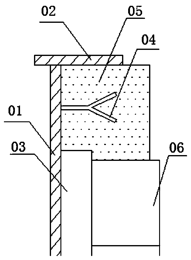
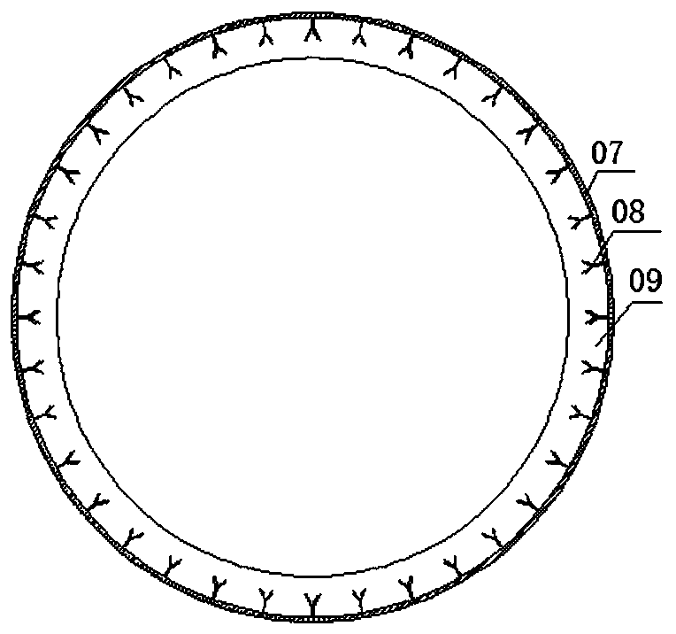
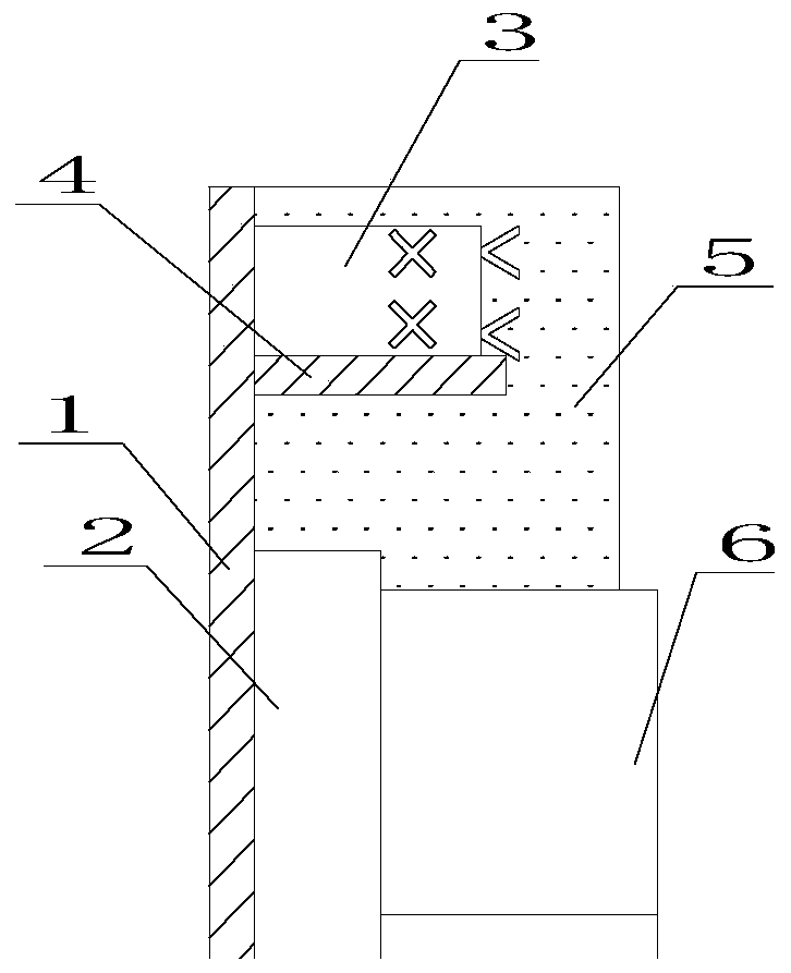
[0021] refer to image 3 and Figure 4 , a pouring structure along the edge of a steel water tank, including the outermost steel structure layer 1, the permanent castable layer 2 located in the middle, the anchor piece 3, the anchor rib plate 4 and the castable layer 5 along the tank, and the innermost working layer Corundum brick6.

[0022] The anchor piece 3 is an anchor plate-like structure, and a whole circle of anchor ribs 4 is welded on the steel struc...


PUM

PropertyMeasurementUnit
widthaaaaaaaaaa
thicknessaaaaaaaaaa

Abstract

The invention discloses a pouring structure for the tank edge of a molten steel tank. The pouring structure comprises a steel structure layer on the outermost layer, a castable permanent layer, anchoring parts, an anchoring rib plate, a tank edge castable layer and a working layer corundum brick. The anchoring parts, the anchoring rib plate and the tank edge castable layer are located in the middle, and the working layer corundum brick is located on the innermost side. The anchoring parts are of anchoring plate platy structures, the whole circle of anchoring rib plate is welded to the portion,in the middle of the tank edge, of the steel structure layer, the anchoring rib plate, anchoring plates and the steel structure layer are welded into a whole, the welding amount and the welding strength are greatly improved, and damage to the anchoring parts in the using and detaching processes is effectively reduced. The V type anchoring parts are additionally welded to the anchoring plates, thedensity of the anchoring parts is improved, and the anchoring effect on castable is enhanced. The structural design is novel, by improving the structures of the anchoring parts, the welding amount and the welding strength are greatly improved, damage to the anchoring parts in the using and detaching processes is effectively reduced, the strength of the castable on the tank edge is enhanced, and the phenomenon of steel permeation caused by a large circular seam of the tank wall is reduced.

Description

【Technical field】 [0001] The invention relates to the field of building and laying of molten steel tanks for steelmaking, in particular to a pouring structure along the molten steel tank. 【Background technique】 [0002] Existing steel ladle tank rim structures are, for example figure 1 As shown, the tank edge structure of the original molten steel tank includes steel structure layer 01, tank edge plate 02, castable permanent layer 03, D-shaped anchor piece 04, tank edge castable layer 05 and corundum brick working layer 06, as shown in figure 2 As shown, the former steel ladle tank includes a steel structure layer 07, a ding-shaped anchor 08 and a corundum brick working layer 09 along the anchor. The defective along the structure of this molten steel tank is that the anchor is welded in the middle, and the anchor is nail-shaped, and the welding amount of the welded part is small, and the firmness is insufficient. [0003] During the operation and use of the molten steel t...

Claims


Application Information

Patent Timeline
Patent Type & Authority Applications(China)
IPC IPC(8): B22D41/00B22D41/02
CPCB22D41/00B22D41/02
Inventor 阮卫民徐小东程永新
Owner 武汉精鼎科技股份有限公司
Why Eureka
Try Eureka