Installing and welding tool for cab
What is Al technical title?
Al technical title is built by PatSnap Al team. It summarizes the technical point description of the patent document.
A technology for assembling welding equipment and driver's cab, which is applied in the field of welding equipment and driver's cab assembly welding equipment, can solve the problems of cab deformation, inconvenient operation, low production efficiency, etc., meet the requirements of guaranteed dimensional accuracy, good versatility, and easy to get rid of the womb Effect
Active Publication Date: 2013-05-29
南京雷尔伟新技术股份有限公司
View PDF8 Cites 0 Cited by
Summary
Abstract
Description
Claims
Application Information
AI Technical Summary
This helps you quickly interpret patents by identifying the three key elements:
Problems solved by technology
Method used
Benefits of technology
Problems solved by technology
In the past, the manual butt joint method was used. This method has a great impact on the deformation of the driver's cab during full welding, affects the welding quality, and causes the potential danger of vehicle accidents, and the production efficiency is low and the operation is inconvenient.
Method used
Image
Click on the blue label to locate the original text in one second.
Reading with bidirectional positioning of images and text.
Examples
Embodiment Construction
[0015] In order to make the technical means, creative features, goals and effects achieved by the present invention easy to understand, the present invention will be further described below in conjunction with specific embodiments.
[0016] This example:
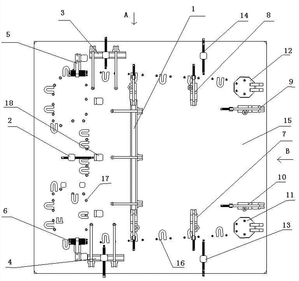
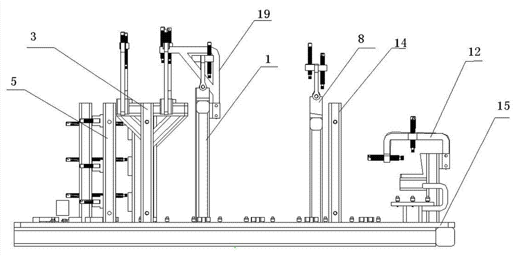
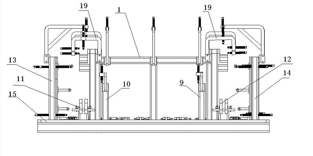
[0017] see figure 1 In order to control the welding deformation as much as possible and ensure the size of the product, it is decided to redesign and manufacture the production and assembly welding tooling suitable for the full-welded driver's cab. The welding-resistant tooling for the driver's cab in this embodiment includes a bottom plate and a three-way pressing and positioning device installed on the bottom plate 1. The middle pressing device of the large floor 2. The anti-collision barrier positioning and pressing device, the left pressing device 5, the right pressing device 6, the curved beam positioning and pressing device, the beam positioning and pressing device, and the end chuck positioning block, door frame pres...
PUM
Abstract
The invention relates to an installing and welding tool for a cab, which comprises a baseplate, a three-direction pressing and positioning device arranged on the baseplate, a large-floor middle pressing device, a crash barrier positioning and pressing device, a left pressing device, a right pressing device, a camber beam positioning and pressing device, a doorframe pressing device, a cross beam positioning and pressing device and an end chuck positioning block, wherein the large-floor middle pressing device, the crash barrier positioning and pressing device, the left pressing device and the right pressing device are arranged on one side of the three-direction pressing and positioning device, the camber beam positioning and pressing device, the doorframe pressing device, the cross beam positioning and pressing device and the end chuck positioning block are arranged on the other side of the three-direction pressing and positioning device, the left pressing device and the right pressing device are respectively arranged on two ends of the three-direction pressing and positioning device, the large-floor middle pressing device is arranged between the left pressing device and the right pressing device, one end of the large-floor middle pressing device is further provided with a large-floor rear positioning device, and the two ends of the three-direction pressing and positioning device are provided with pressing and positioning mechanisms. By means of the invention, the vertical dimensions of end parts of a cross beam and a camber beam are ensured, the cross beam is prevented fromlateral bending, and the installing and welding tool has the advantages of convenience for operation and bodilessness, good generality and capability of clamping manually and is convenient, flexible and reliable to mount and dismount.
Description
technical field [0001] The invention relates to a welding tool, in particular to a driver's cab assembly welding tool, which belongs to the technical field of welding devices. Background technique [0002] In the welding process of the driver's cab of the railway vehicle, it is currently used to perform tack welding first, and then perform full welding. Spot welding is used to position parts. In the past, the manual butt joint method was used. This method has a great impact on the deformation of the driver's cab during full welding, affects the welding quality, and causes the potential danger of vehicle accidents, and the production efficiency is low and the operation is inconvenient. Contents of the invention [0003] In order to overcome the defects in the prior art, the purpose of the present invention is to provide a driver's cab welding tool that can adjust the positioning according to the degree of welding deformation of the product. It is manually clamped, easy to ...
Claims
Application Information
Patent Timeline
Application Date:The date an application was filed.
Publication Date:The date a patent or application was officially published.
First Publication Date:The earliest publication date of a patent with the same application number.
Issue Date:Publication date of the patent grant document.
PCT Entry Date:The Entry date of PCT National Phase.
Estimated Expiry Date:The statutory expiry date of a patent right according to the Patent Law, and it is the longest term of protection that the patent right can achieve without the termination of the patent right due to other reasons(Term extension factor has been taken into account ).
Invalid Date:Actual expiry date is based on effective date or publication date of legal transaction data of invalid patent.