Machine tool

A technology of machine tools and racks, applied in the direction of metal processing mechanical parts, metal processing equipment, manufacturing tools, etc., to achieve the effect of accuracy improvement, improved processing accuracy and dimensional stability, and high feed

Active Publication Date: 2011-08-17
DECKEL MAHO SEEBACH GMBH
View PDF12 Cites 20 Cited by
  • Summary
  • Abstract
  • Description
  • Claims
  • Application Information

AI Technical Summary

Problems solved by technology

In addition to this, changes in the curvature of the protruding console part due to its own weight as well as the weight of the workpiece during its rotation about the horizontal axis of rotation may have adverse effects

Method used


Image

  • Machine tool
  • Machine tool
  • Machine tool

Examples


Embodiment Construction

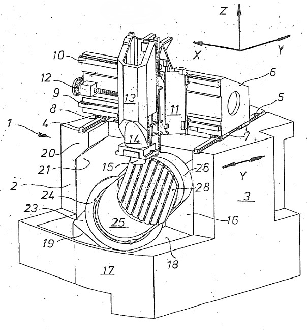
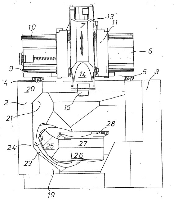
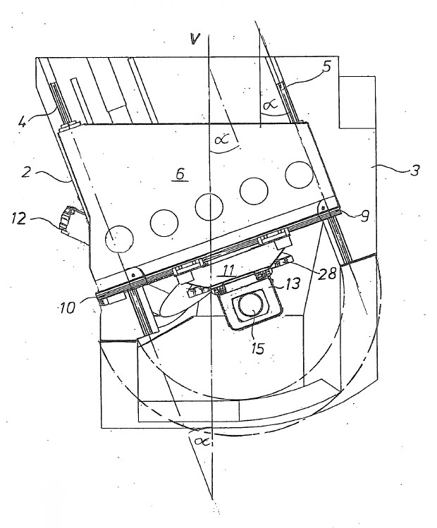
[0028] , the machine tool shown in the various views of FIG. 1 is implemented in a gantry configuration and includes a program control unit (not shown) as well as eg a tool changer and other additional units. The machine frame 1 is preferably realized in one-piece construction in order to achieve the required high rigidity. The two side walls 2 , 3 extend parallel to the Y coordinate axis and carry on their top sides horizontal guide rails 4 , 5 as part of a linear guide for the transverse slide 6 , which can be accessed via guide shoes 7 , 8 The transverse slide 6 is guided in a displaced manner on the guide rails 4 , 5 . An electric motor comprising a shaft drive or a linear motor is used as the drive for the displacement movement of the transverse slide 6 forming a crosshead spanning the two side walls 2 , 3 . On the face of the transverse slide 6 , the slide 11 is guided in two vertically spaced guide rails 9 , 10 by means of a motorized drive unit 12 so as to be displace...


PUM


Abstract

The invention relates to a machine tool comprising frame (1) which has rigid side walls (2, 3) with linear guides (4, 5) on the top; compound slides (6, 11) which is movable and situated in or on the linear guides (4, 5) of the side walls, and which guides a processing unit (14) with a spindle head (15) at a front side so as to move the processing unit (14) vertically; and workpiece holding units (24-28) which are arranged in a gap between the side walls and may include a workbench (28) or a workpiece clamping device. One side wall (3) at the front side is shorter than the other side wall (2) for forming an enlarged access to a working space of the machine tool. The linear guides (4, 5) on the side walls (2, 3) of a machine frame (1) are aligned under an acute angle to a vertical center plane of the machine frame (1).

Description

technical field [0001] The invention relates to a machine tool comprising: a frame with dimensionally rigid side walls containing horizontal linear guides on the top side; moving in the linear guides of the side walls, guiding the processing unit including the shaft head in front of the composite slide so as to make it vertically displaceable; and the workpiece mounting unit, which is arranged in the space between the side walls , the workpiece mounting unit may have a workpiece table or a workpiece clamping device. Background technique [0002] Machine tools of this type comprising two dimensionally rigid parallel side walls, a transverse slide displaceable on guides on the top surfaces of the side walls, and a front machining unit that can be equipped with cutting tools are so-called gantry machines . Usually, in machines of this type, a crosshead is formed by a transverse slide moving on the Y axis on parallel rails on the two side walls and supports a longitudinal slid...

Claims


Application Information

Patent Timeline
Patent Type & Authority Applications(China)
IPC IPC(8): B23Q1/01B23Q1/48B23Q1/28
CPCB23Q1/012B23Q1/015B23Q1/54Y10T409/305824Y10T409/307Y10T409/307056Y10T409/307672Y10T409/307728Y10T409/30784Y10T409/308288Y10T409/30896Y10T409/309576
Inventor 乌多·图尔曼马蒂亚斯·布兰德
Owner DECKEL MAHO SEEBACH GMBH
Why Eureka
Try Eureka