Steel structural panel sand gravel dam

A sand and gravel dam and steel structure technology, applied in the field of sand and gravel dams, can solve the problems of difficult construction of concrete face dams, large amount of materials, and large environmental impacts, and achieve good adaptation to terrain conditions, low performance requirements, and reduced environmental damage Effect

Active Publication Date: 2011-08-17
NORTH CHINA UNIV OF WATER RESOURCES & ELECTRIC POWER
View PDF5 Cites 8 Cited by
  • Summary
  • Abstract
  • Description
  • Claims
  • Application Information

AI Technical Summary

Problems solved by technology

[0003] In order to overcome the disadvantages of concrete face dam construction difficulty, large investment, large amo

Method used


Image

  • Steel structural panel sand gravel dam
  • Steel structural panel sand gravel dam
  • Steel structural panel sand gravel dam

Examples


Embodiment 1

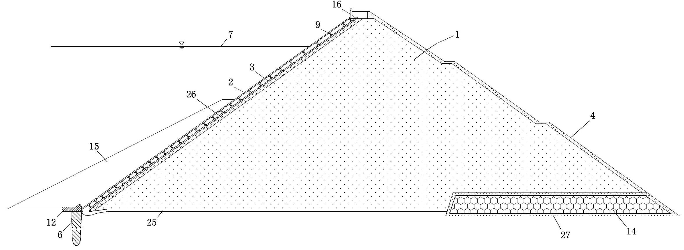
[0034] Embodiment one: see figure 1 — Figure 4 , Figure 7 , a steel structure face gravel dam, comprising a dam body 1 filled with soil and gravel, a cut-off wall 6 is provided under the riverbed on the upstream surface of the dam body 1, a slope protection 4 is arranged downstream of the dam body 1, and the dam body 1 The upstream facing surface is set as a steel structure composite panel. The anti-seepage structure composed of the steel structure composite panel, the toe boards 11 on both banks and the toe board 12 of the river bed.

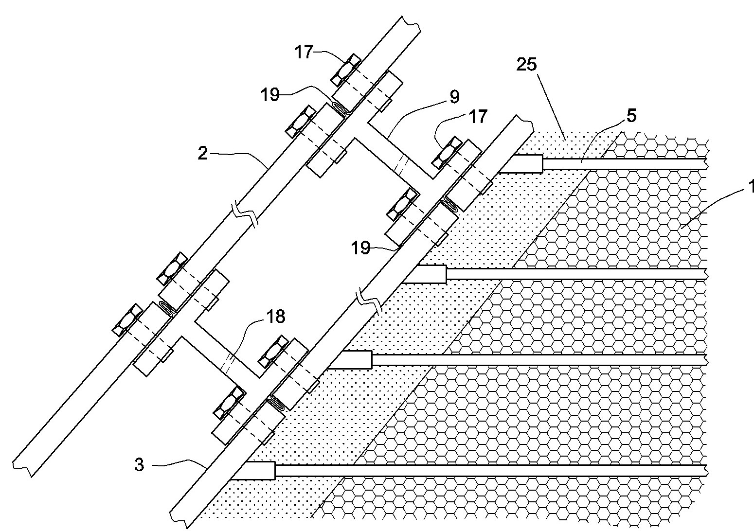
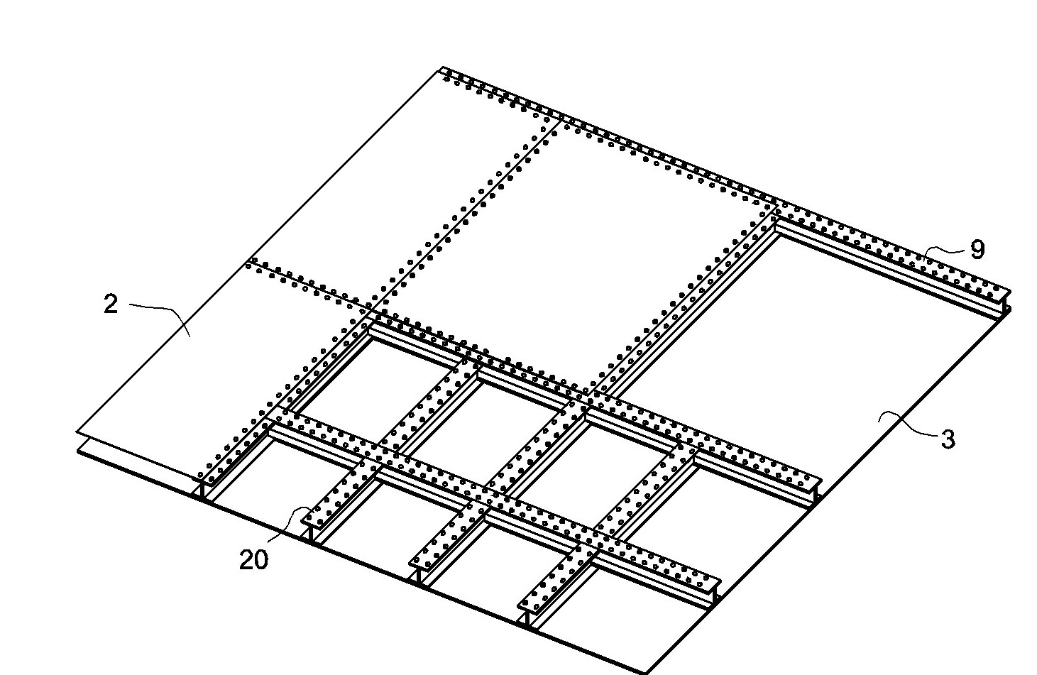
[0035] The composite panel of the steel structure includes an inner layer composite steel plate 3 and an outer layer composite steel plate 2, and a supporting frame 9 is arranged between the two layers of composite steel plates. The inner steel plate is composed of a number of rectangular single-piece steel plates that are butt-jointed, sealed and fixed by multiple weather-resistant steel plates, and is attached to the water facing surface...

Embodiment 2

[0041] Embodiment two: see Figure 5 , the content is basically the same as that of Embodiment 1, and the similarities will not be repeated. The difference is that the I-shaped steel bar is formed by two channel steels fixed by bolts or welded.

Embodiment 3

[0042] Embodiment three: see Figure 6 , the content is basically the same as that of Embodiment 1, and the similarities will not be repeated. The difference is that fixed bolts are vertically fixed on the outer surface of the inner single-piece steel plate, and the lower flange of the I-shaped steel is provided with a through hole for use. There is a layer of sealing sheet between the I-shaped steel bar and the inner single-piece steel plate, and the through hole is matched and set on the corresponding fixed bolt, and the end of each fixed bolt is fixed with a nut; the upper flange of the I-shaped steel is fixed vertically There are fixed bolts, the outer monolithic steel plate is provided with opposite through holes, and a layer of sealing sheet is placed between the outer monolithic steel plate and the I-shaped steel bar. And the through hole is set on the corresponding fixed bolt, and the end of each fixed bolt is fixed with a nut.


PUM

PropertyMeasurementUnit
Thicknessaaaaaaaaaa
Thicknessaaaaaaaaaa

Abstract

The invention relates to a steel structural panel sand gravel dam, which comprises a dam body and a drainage system thereof, a seepage preventing structure and a downstream protection slope. A steel structural combined panel on the upstream water surface of the dam body comprises steel plates of inner and outer layers and a supporting skeleton between the steel plates, the water back surface of the single steel plate of the inner layer is transversely provided with a plurality of fixed insertion ribs inserted into the damp body, and a layer is anticorrosion seepage-proof coating polyurea material is assisted on all the surfaces of the steel structural combined panel, the insertion ribs and butted seams or connecting bolts. The dam simultaneously has the advantages of a gravity dam and a steel structured dam, and the inner plates and the dam body are combined into a whole so that the dam is firmer. The dam is stable and easily built, has flexible structural form, can better adapt to the topographic conditions, has low requirements for damming materials, can be built by using multiple building materials, reduces environmental destroy due to damming, can be processed in batch in a factory, has high field construction speed, and is convenient for maintenance or replacement.

Description

technical field [0001] The invention relates to a sand and gravel dam in the technical field of water conservancy, in particular to a steel structure face sand and gravel dam. Background technique [0002] The traditional face dam refers to the dam type composed of rockfill (or gravel) and anti-seepage face. Corresponding temperature control measures should be taken during the construction of concrete panels in winter and summer to avoid harmful cracks, which increases the difficulty and investment of construction. Moreover, the concrete slab is prone to cracks, which is very unfavorable to the stability of the dam structure. Once there is a problem with the concrete panel, there are problems such as difficult maintenance. Contents of the invention [0003] In order to overcome the shortcomings of concrete face dams such as high construction difficulty, large investment, large material consumption and great impact on the environment, the invention provides a steel struct...

Claims


Application Information

Patent Timeline
IPC IPC(8): E02B7/06
Inventor 魏群张国新刘尚蔚尹伟波姜华
Owner NORTH CHINA UNIV OF WATER RESOURCES & ELECTRIC POWER
Why Eureka
Try Eureka