Turboramjet combined engine based on knocking combustion
A technology of turbo ramming combination and detonation engine, which is applied in the direction of combined engine, ramjet engine, mechanical equipment, etc., can solve the problems of long machine size, complex structure and many parts, etc. The effect of improving propulsion performance
- Summary
- Abstract
- Description
- Claims
- Application Information
AI Technical Summary
Problems solved by technology
Method used
Image
Examples
Embodiment 1
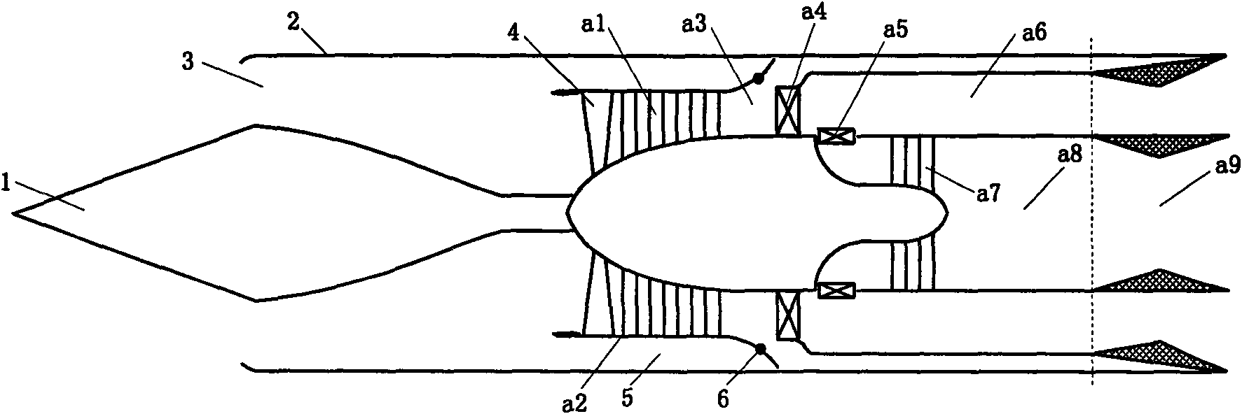
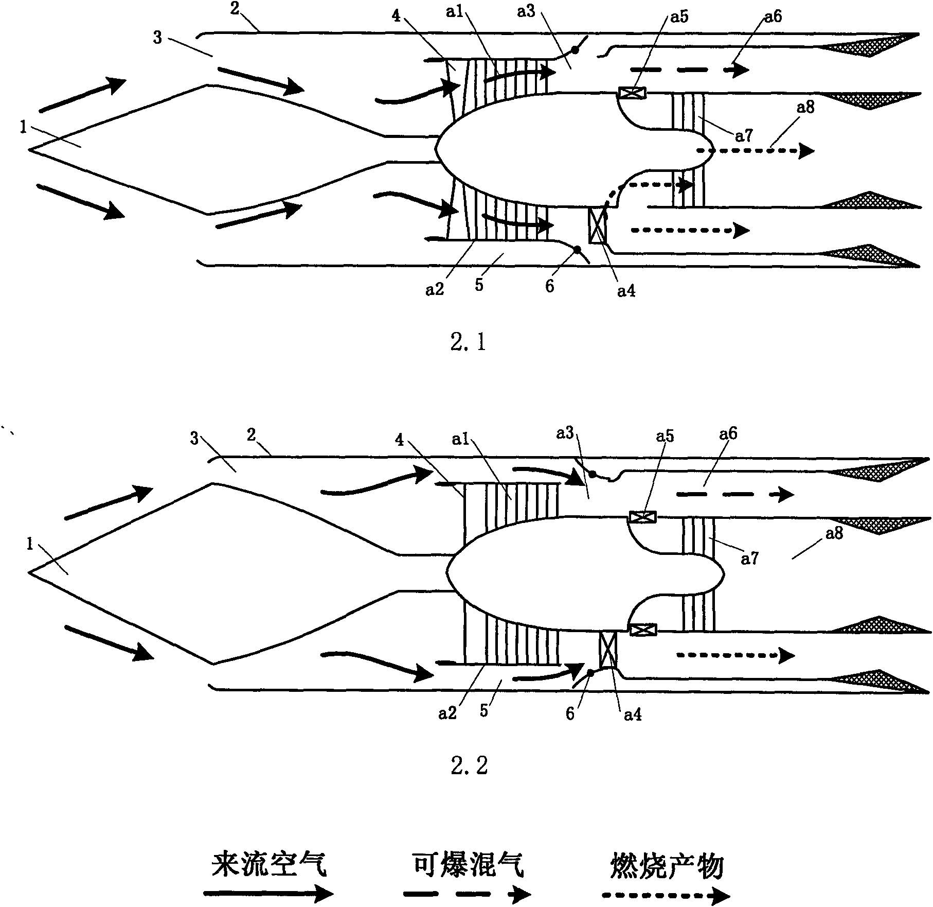
[0020] like image 3 As shown, it includes a front turbine combined pulse detonation engine a, an adjustable center cone 1, a complete machine housing 2, an adjustable air inlet 3, an adjustable inlet guide vane 4, an air duct 5 and an adjustable plate 6a , along the airflow direction of the combined engine, the adjustable central cone 1 is located at the front end of the engine, and the ring cavity surrounded by the whole machine casing 2 forms an adjustable air inlet 3, and the downstream of the adjustable central cone 1 is connected to the front turbine Combined pulse detonation engine a, upstream along the compressor casing a2 of the long front turbine combined pulse detonation engine, at least one stage of compressor length, combined pulse detonation in the long compressor casing a2 and the front turbine The upstream of the compressor a1 of the engine is installed with adjustable inlet guide vanes 4, the compressor case a2 of the combined pulse detonation engine with the ...
Embodiment 2
[0022] like Figure 4 As shown, it includes a front turbine combined pulse detonation engine a, an adjustable center cone 1, a complete machine casing 2, an adjustable air inlet 3, an adjustable inlet guide vane 4, an air duct 5 and an adjustable plate 6b , along the airflow direction of the engine, the adjustable central cone 1 is located at the front end of the engine, and the ring cavity surrounded by the whole machine casing 2 forms an adjustable air inlet 3, and the downstream of the adjustable central cone 1 is connected to the pre-turbine combination Pulse detonation engine a, upstream along the compressor casing a2 of the long front turbine combined pulse detonation engine with at least one stage of compressor length, in the long compressor casing a2 and the front turbine combined pulse detonation engine The upstream of the compressor a1 is equipped with adjustable inlet guide vanes 4, and the compressor case a2 of the front turbine combined pulse detonation engine and...
Embodiment 3
[0024] like Figure 5 As shown, it includes a front turbine combined pulse detonation engine a, an adjustable center cone 1, a complete machine casing 2, an adjustable air inlet 3, an adjustable inlet guide vane 4, an air duct 5 and an adjustable plate 6b , Cooling air duct 7, mixer 8 and nozzle 9. Along the airflow direction of the engine, the adjustable central cone 1 is located at the front end of the engine, and the ring cavity surrounded by the whole machine casing 2 forms an adjustable air inlet 3, and the downstream of the adjustable central cone 1 is connected to the front turbine combination pulse The detonation engine a, upstream along the compressor case a2 of the long pre-turbine combination pulse detonation engine, at least one stage of compressor length, in the long compressor case a2 and the pre-turbine combination pulse detonation engine The adjustable inlet guide vane 4 is installed upstream of the compressor a1, and the compressor casing a2 of the front turb...
PUM
 Abstract
Description
Claims
Application Information
 - R&D
- Intellectual Property
- Life Sciences
- Materials
- Tech Scout
- Unparalleled Data Quality
- Higher Quality Content
- 60% Fewer Hallucinations
Browse by: Latest US Patents, China's latest patents, Technical Efficacy Thesaurus, Application Domain, Technology Topic, Popular Technical Reports.
© 2025 PatSnap. All rights reserved.Legal|Privacy policy|Modern Slavery Act Transparency Statement|Sitemap|About US| Contact US: help@patsnap.com


