
Hydraulic system of crane and shock-resistance valve thereof

An anti-shock, valve cavity technology, applied in the field of crane hydraulic system and anti-shock valve, can solve problems such as pressure rise, pressure fluctuation, system pressure change, etc., to achieve the effect of fast response

Inactive Publication Date: 2011-08-17
XUZHOU HEAVY MASCH CO LTD
View PDF4 Cites 6 Cited by
  • Summary
  • Abstract
  • Description
  • Claims
  • Application Information

AI Technical Summary

Problems solved by technology

[0003] The components of the hydraulic system are connected by pipelines. Based on various factors, the system will produce pressure fluctuations, such as the following reasons: when the load changes, because the signal transmission of the feedback oil circuit takes a certain time, the change of the load cannot be timely If it is transmitted to the displacement control unit of the power element, the pressure of the system may rise during this transmission time, resulting in hydraulic shock; even if the feedback oil circuit transmits the feedback signal to the displacement control unit in time, the displacement control unit also needs a certain Response time, the flow rate cannot be adjusted in time as required. For example, when the system is started and the pressure of the main oil circuit is established before the feedback pressure, the hydraulic pump as the power element will swing to the maximum displacement. With the establishment of the feedback pressure, The displacement of the hydraulic pump will automatically adapt to the flow demand of the control main valve, that is, the hydraulic pump will change to a small displacement to meet the demand of the control main valve, but due to the inertia limitation of the hydraulic pump itself, it may not be able to reduce the displacement in time The direction swings, and the flow and pressure are in a coupled relationship. At this time, a high pressure will be established in the main oil circuit, resulting in hydraulic shock; moreover, the power element itself will have certain output fluctuations based on its working principle, for example, the gear Both the pump and the plunger pump have certain pulsation problems, and this problem cannot be solved by the feedback oil circuit; in addition, external natural changes such as changes in the deformation and recovery of the rigid mechanism, and changes in dynamic and static states will also cause changes in the system pressure. form a hydraulic shock

Method used


Image

  • Hydraulic system of crane and shock-resistance valve thereof
  • Hydraulic system of crane and shock-resistance valve thereof
  • Hydraulic system of crane and shock-resistance valve thereof

Examples


Embodiment Construction

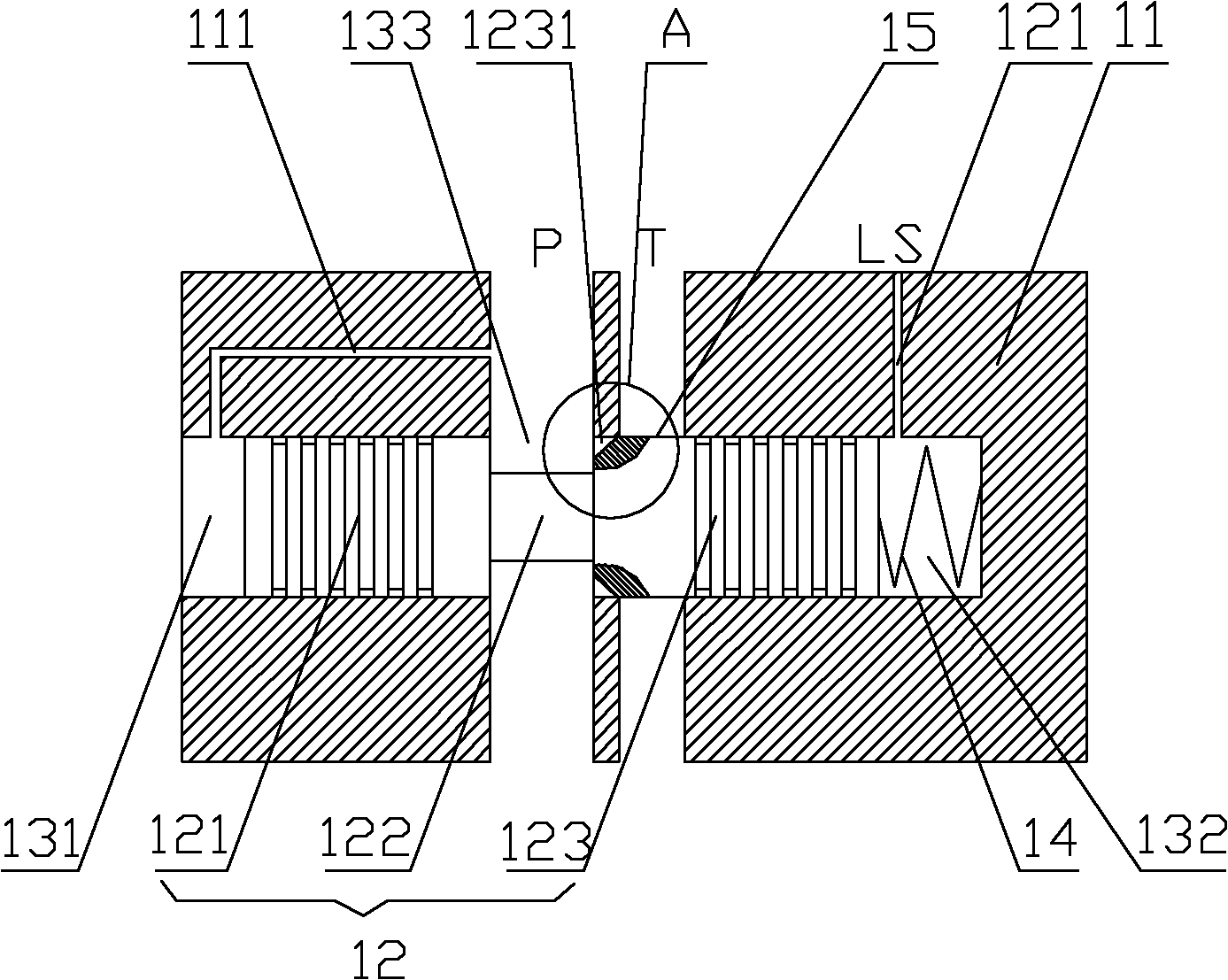
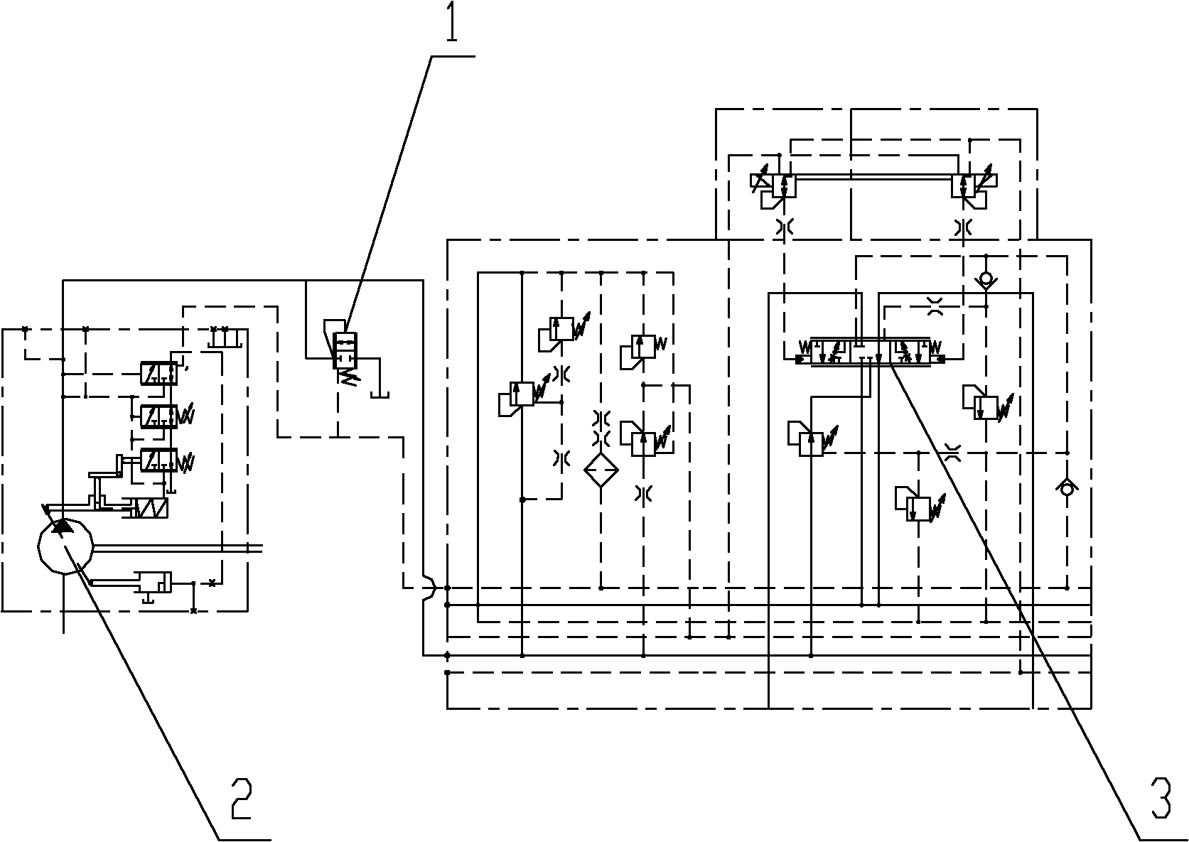
[0022] A core of the present invention is to provide an anti-shock valve, which can unload the shock pressure of the system in time by comparing the pressure of the main oil circuit and the feedback oil circuit, and play an anti-shock effect, thereby maintaining the system Stable pressure. Another core of the present invention is to provide a crane hydraulic system including the anti-shock valve.

[0023] In order to enable those skilled in the art to better understand the technical solutions of the present invention, the present invention will be further described in detail below in conjunction with the accompanying drawings and specific embodiments. For ease of understanding, the following embodiments describe the anti-shock valve in the overall crane hydraulic system. For the crane hydraulic system provided by the present invention, its specific embodiments and beneficial effects are also reflected in the following embodiments. No longer discussed separately. Of course, t...


PUM


Abstract

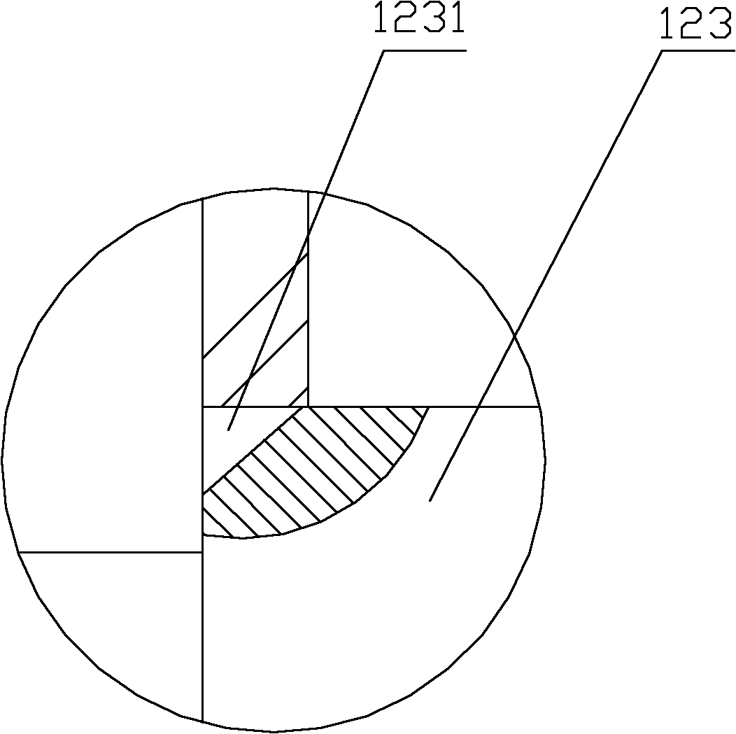
The invention discloses a shock-resistance valve. A valve body of the shock-resistance valve is provided with an oil inlet, an oil return opening and a feedback oil opening; a valve chamber of the shock-resistance valve is provided with a regulating valve plug internally which controls the connection and disconnection of the oil inlet and the oil return opening; the valve chamber comprises a left chamber and a right chamber which are formed by the separation of the regulating valve plug; the oil inlet is communicated with the left chamber; the feedback oil opening is communicated with the right chamber; and an elastic component is arranged between the regulating valve plug and the axial chamber wall of the right chamber. The oil inlet of the shock-resistance valve is communicated with a main oil way; the feedback oil opening is communicated with a feedback oil way; when the pressure of the main oil way is increased abruptly, the pressures which acts on two sides of the regulating valve plug are different, when the pressure difference exceeds a set value of a pressure-regulating spring, a communicated oil opening of the oil return opening and the oil inlet is opened, the hydraulic oil of the main oil way flows back the oil return tank from the oil return opening for unloading, thus the role of shock-resistance is played; and the shock-resistance valve is directly communicated with the main oil way, the pressure peak value of the main oil way can be timely cut down, and shock-resistance is realized timely. The invention also discloses a hydraulic system of a crane comprising the shock-resistance valve.

Description

technical field [0001] The invention relates to the technical field of engineering machinery, in particular to an anti-shock valve. The present invention also relates to a crane hydraulic system comprising the above-mentioned anti-shock valve. Background technique [0002] The hydraulic system is mainly composed of power components, control main valves, actuators and some auxiliary devices. In order to stabilize the hydraulic system, it is usually necessary to set up a feedback oil circuit, which is generally fed back in the form of pressure. The power element has a displacement control unit, and the feedback oil circuit feeds back the feedback signal of the system pressure value to the displacement control unit, and the displacement control unit can reasonably control the displacement of the power element according to the feedback signal, thereby stabilizing the hydraulic system. [0003] The components of the hydraulic system are connected by pipelines. Based on various f...

Claims


Application Information

Patent Timeline
Patent Type & Authority Applications(China)
IPC IPC(8): F15B13/02F15B13/16
Inventor 史先信刘邦才王清送
Owner XUZHOU HEAVY MASCH CO LTD
Learn More