Sub-surface damage detection method based on temperature field finite element analysis and simulation

A sub-surface damage and detection method technology, applied in the direction of measuring devices, instruments, etc., can solve the problems of high cost and low precision, and achieve the effects of low cost, simple equipment operation and short detection cycle

Inactive Publication Date: 2011-08-17
XI AN JIAOTONG UNIV
View PDF4 Cites 9 Cited by
  • Summary
  • Abstract
  • Description
  • Claims
  • Application Information

AI Technical Summary

Problems solved by technology

Photothermal microscopy and X-ray diffraction overcome some of the disadvantages

Method used


Image

  • Sub-surface damage detection method based on temperature field finite element analysis and simulation
  • Sub-surface damage detection method based on temperature field finite element analysis and simulation
  • Sub-surface damage detection method based on temperature field finite element analysis and simulation

Examples


Embodiment Construction

[0022] The depth of the subsurface damage layer produced by the grinding process of optical materials can directly affect the long-term stability, service strength and laser damage resistance threshold of optical parts. Therefore, it is extremely important to non-destructively detect subsurface damage of optical parts. The present invention will be described in further detail below in conjunction with specific examples.

[0023] The subsurface damage detection method based on the finite element analysis and simulation of the temperature field includes the following steps:

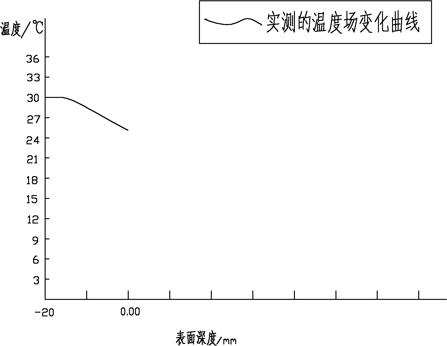
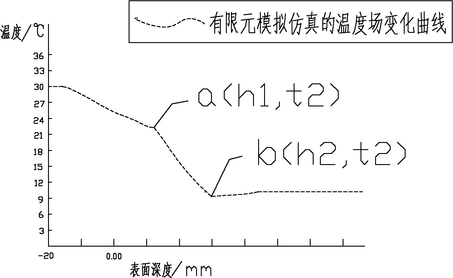
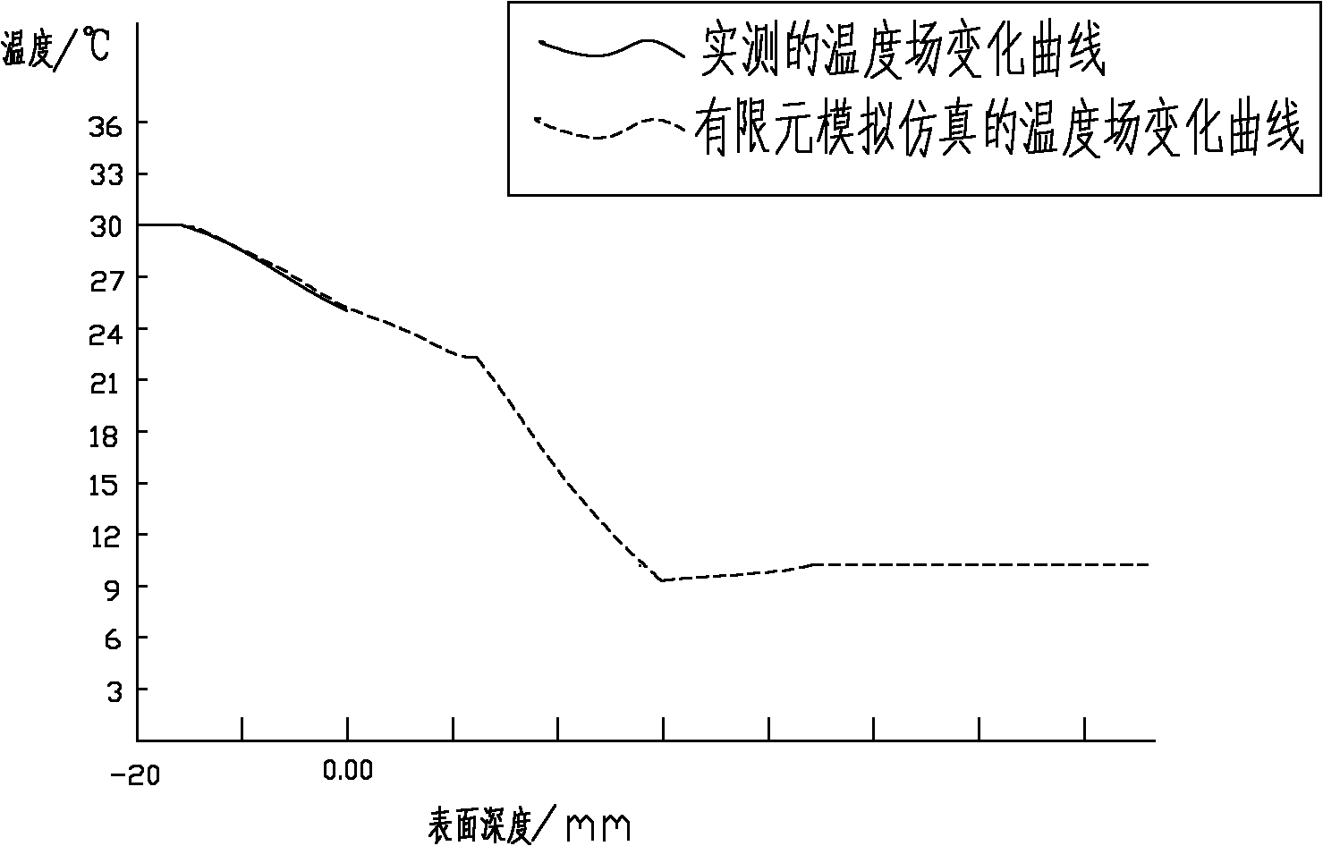
[0024] (1) Set the heating constant temperature source T1 (10°C) on the upper surface of the optical k9 glass part, and set the heating constant temperature source T2 (30°C) on the lower surface with a heating plate, T2>T1, the temperature difference between the upper and lower surfaces of the constant temperature source is 20°C, Heat for a period of time until the heat transfer reaches a dynamic equilibri...


PUM


Abstract

The invention discloses a sub-surface damage detection method based on temperature field finite element analysis and simulation. The method is characterized in that when a constant-temperature heat source is respectively added to the upper surface and the lower surface of a part, the temperature field distribution curve of the basal body of the part has two turning points which respectively correspond to the upper end and the lower end of a crack. The method comprises the following steps of: respectively adding a constant-temperature heat source to the upper surface and the lower surface of the part, detecting the stabilized temperature field distribution of the upper surface of the part by using a high-resolution scanning thermal probe to obtain an actually-measured temperature field change curve; establishing a three-dimensional model of a part with sub-surface damage cracks with different depths, and carrying out the finite element analysis and simulation of the temperature field distribution of the model of the part to obtain a simulated temperature field change curve; and finally determining the depth of the damage cracks according to the turning points of the simulated temperature field change curve by calculating and analyzing the relative error of the actually-measured temperature field distribution curve and the simulated temperature field distribution curve. The method can be used to detect the depth of the sub-surface damage cracks of the part in a short period with low cost under the condition of not damaging the part.

Description

technical field [0001] The invention relates to a method for non-destructive sub-surface quality detection of parts in the field of optical ultra-precision machining, in particular to a sub-surface damage detection method based on temperature field finite element analysis and simulation. Background technique [0002] The processing and forming of optical parts (such as: camera lenses, lenses, telescopes and mirrors) generally undergoes traditional processing procedures such as grinding and polishing. However, in the process of grinding optical glass, abrasive grains can be regarded as pressure heads of different sizes and uneven distribution. According to the indentation fracture mechanics model, the indenter exerts a certain pressure on the surface of the optical material. Therefore, in the interaction between the indenter and the optical material, the optical material directly under the indenter will produce an inelastic deformation zone (plastic deformation zone). When t...

Claims


Application Information

Patent Timeline
IPC IPC(8): G01B21/18
Inventor 王海容王健云蒋庄德苑国英
Owner XI AN JIAOTONG UNIV
Why Eureka
Try Eureka