Piston ring radial pressure detection device and detection method thereof

A technology of radial pressure and detection device, used in measurement devices, force/torque/work measuring instruments, instruments, etc., can solve the problems of pressure in and out, lengthened design cycle, backwardness, etc., and achieve the effect of accurate detection structure and simple steps

Inactive Publication Date: 2011-08-17
CRRC QISHUYAN INSTITUTE CO LTD
View PDF5 Cites 3 Cited by
  • Summary
  • Abstract
  • Description
  • Claims
  • Application Information

AI Technical Summary

Problems solved by technology

[0006] At present, the domestic technology for detecting the pressure distribution of piston rings is relatively backward. Many factories use the piston rings to work for a long time to conduct destructive experiments, which greatly lengthens the product design cycle and increases the design cost of new products.
In addition, the thin-wall cylinder test device disclosed in Chinese patents ZL90100553 and ZL200820038515.0 is used to test the distribution pressure of the piston ring through the pressure sensor arranged on the thin wall side. The test device of this structure can only detect intermittent, piston ring The pressure values ​​at different points, rather than the actual continuous pressure distribution of the piston ring in the cylinder; and affected by the dimensional accuracy of the thin-walled cylinder, the measured pressure will have a large discrepancy

Method used


Image

  • Piston ring radial pressure detection device and detection method thereof
  • Piston ring radial pressure detection device and detection method thereof
  • Piston ring radial pressure detection device and detection method thereof

Examples


Embodiment Construction

[0034] The present invention is described in detail below by preferred embodiments of the present invention:

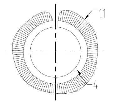
[0035] Such as figure 1 Shown is the pressure distribution diagram of each point of the piston ring after receiving pressure compression, figure 1 The length of the radial line segment outside each point of the outer circle of the middle piston ring 4 represents the pressure value 11 of each point, and the pressure distribution of each point of the piston ring 4 is obtained by connecting the ends of these radial line segments. When the piston is loaded into the cylinder, it is compressed and elastically deformed. However, the radii of each point on the outer circle of the piston ring 4 are different, such as figure 1 As shown, the pressure value 11 produced by each point on the cylinder is also different. Since the pressure value 11 of each point is determined by the radius of the point, the pressure detection device of the present invention provides accurate basic ...


PUM


Abstract

The invention provides a piston ring radial pressure detection device comprising a measuring table, flexible element, a fixed end, an adjustment end and a fixture, wherein the flexible element is wound on the periphery of a piston ring; the fixed end is arranged on the measuring table; one end of the flexible element is connected with the fixed end; the adjustment end is arranged on the measuring table; the other end of the flexible element is connected with the adjustment end and can be operationally driven to move by the adjustment end; and the fixture is used for clamping the piston ring operationally. The invention has the beneficial effects that the piston ring is compressed to an actual working state by using a frock clamp, the radius increment of each point is measured when the piston ring is in work, and the actual continuous pressure distribution of the piston ring is obtained further; the detection structure is accurate, and the steps are simple.

Description

technical field [0001] The invention relates to the technical field of mechanical measurement, in particular to a piston ring radial pressure detection device and a detection method thereof. Background technique [0002] Piston ring is a key part of internal combustion engine, air compressor and other machines. It is installed on the piston of the cylinder and plays the roles of sealing, oil scraping, heat transfer and support. [0003] The basic shape of the piston ring is a non-circular ring with a gap. When it is working, it is nested and installed in the ring groove of the piston to form a perfect circle, and it is closely matched with the cylinder wall by the elastic force generated by its own deformation. The shape of the piston ring in the free state determines the pressure distribution in the cylinder wall, and directly affects the performance of the internal combustion engine such as power, fuel consumption, noise, and cylinder life. Its machining accuracy is an imp...

Claims


Application Information

Patent Timeline
Patent Type & Authority Applications(China)
IPC IPC(8): G01L5/00
Inventor 赵文鑫姚俊杰
Owner CRRC QISHUYAN INSTITUTE CO LTD
Why Eureka
Try Eureka