Vibration table fixture capable of accurately adjusting center of gravity

A vibrating table and fixture technology, used in vibration testing, machine/structural component testing, measuring devices, etc., can solve problems such as the inability to guarantee large specimens and fixtures, the damage of the moving ring of the electric vibrating table, and the fatigue failure of the sealing ring. , to achieve the effect of small difference in vibration value, less installation time, and improved efficiency

Inactive Publication Date: 2011-08-17
ZHEJIANG UNIV
View PDF5 Cites 8 Cited by
  • Summary
  • Abstract
  • Description
  • Claims
  • Application Information

AI Technical Summary

Problems solved by technology

However, the importance of special fixtures for large-scale specimens is generally not paid enough attention at present. The designed test fixtures cannot ensure that the overall center of gravity composed of large specimens and fixtures coincides with the central axis of the shaking table. The vibration transmitted by such fixtures often has a large gap. Distortion, when the vibration is excited in the vertical direction, it is easy to cause the shaking of the vibrating table, resulting in distortion of the vibration waveform, and even damage to the moving coil of the electric vibrating table or premature fatigue failure of the sealing ring of the oil cylinder of the hydraulic vibrating table
The invention can not only ensure that the center of gravity of the test piece passes through the center of the vibrating table surface to reduce the influence of the overturning moment, but also realize the rigid connection between the test piece and the vibrating table table or fixture. the fixture

Method used


Image

  • Vibration table fixture capable of accurately adjusting center of gravity
  • Vibration table fixture capable of accurately adjusting center of gravity
  • Vibration table fixture capable of accurately adjusting center of gravity

Examples


Embodiment Construction

[0018] The present invention will be described in detail below in conjunction with the accompanying drawings.

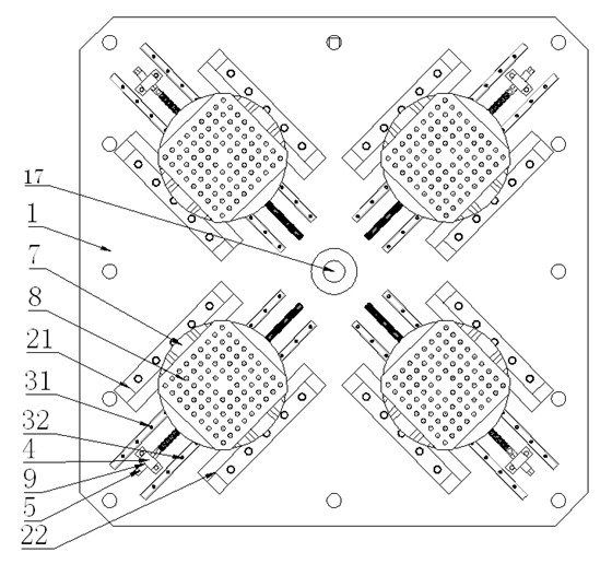
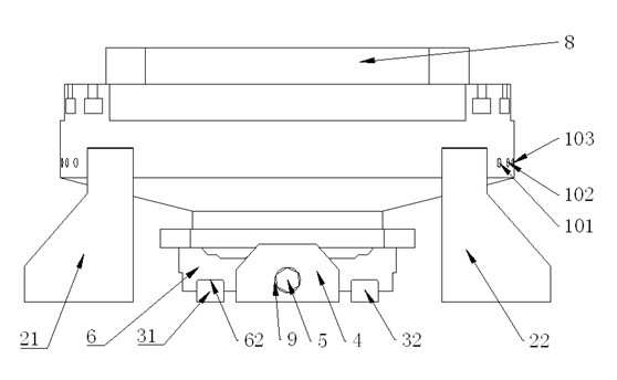
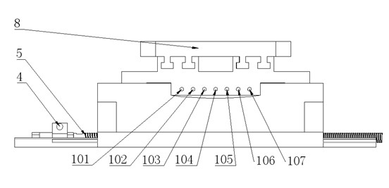
[0019] Such as Figures 1 to 7 As shown, the vibrating table clamp that can be precisely adjusted in the present invention includes a vibrating table top 1 and four sub-clamps. Each sub-fixture contains two guide support plates 21, 22 parallel to each other. On the one hand, the guide support plates can play a guiding role; To resist the overturning moment, two sliding bars 31, 32 parallel to each other are arranged between the two guiding support plates 21, 22, and a supporting block 4 is arranged between the two sliding bars 31, 32, and the guiding supporting plates 21, 22 , the sliding bars 31, 32 and the support block 4 are fixedly connected to the vibrating table top 1 respectively. Each sub-fixture also includes leading screw 5, slide block 6, support plate 7 and base 8, and support block 4 is provided with through hole 41, and a bearing 9 is installed in thi...


PUM


Abstract

The invention discloses a vibration table fixture capable of accurately adjusting the center of gravity, comprising a vibration table top and four subsidiary fixtures in same structures, wherein each subsidiary fixture comprises two guiding supporting plates, two sliding bars, a supporting block, screws, a sliding block, a supporting disc and a base; the four subsidiary fixtures are symmetrically distributed by using a center hole of the vibration table top as the center; the center lines of the screws of every two adjacent subsidiary fixtures form an included angel of 90 degrees; and the center lines of the screws of every two opposite subsidiary fixtures coincide with each other. By using the invention, the base can be adjusted in two degrees of freedom relative to the vibration table top, and the coincided centers of gravity of both a large test piece arranged on the base and the vibration table fixture can coincide with the axis of the vibration table when the large test piece is under the vibration test. The invention can ensure that the center of gravity of the test piece passes by the center of the vibration table top to reduce the influence of the overturning moment and can realize the rigid connection of the test piece and the vibration table top or the vibration table fixture.

Description

technical field [0001] The invention relates to a vibrating table fixture, which can be widely used in the vibration test field as a transport tool such as a container or a fixture for a large test piece, especially the vibration test of large test pieces such as ships and aerospace. Background technique [0002] Vibration test was developed from the aerospace sector, and now it is extended to various industrial sectors such as power machinery, transportation, and construction. With the improvement of reliability requirements for products, especially ships and aerospace products, the development of vibration test system, which is the key equipment of reliability test, is becoming more and more important. The fixture is a device for fixing the test piece on the working table of the vibrating table and transmitting the vibration of the vibrating table to the test piece. Its quality is directly related to the quality of the test. However, the importance of special fixtures for...

Claims


Application Information

Patent Timeline
Patent Type & Authority Applications(China)
IPC IPC(8): G01M7/02
Inventor 陈章位文祥
Owner ZHEJIANG UNIV
Why Eureka
Try Eureka