Method for establishing cable bridge network by using relational database

A cable tray and database technology, applied in electrical digital data processing, special data processing applications, electrical components, etc., to reduce the complexity and error rate of manual judgment, improve work efficiency and quality of results, and solve the effect of repeated calculations

Active Publication Date: 2013-01-02
CHINA NUCLEAR POWER ENG CO LTD
View PDF0 Cites 2 Cited by
  • Summary
  • Abstract
  • Description
  • Claims
  • Application Information

AI Technical Summary

Problems solved by technology

[0010] The purpose of the present invention is to provide a method for constructing a cable tray network using a relational database, to solve the above-mentioned problems in the existing bridge network, and to improve the efficiency and design quality of computer-aided cable laying design work

Method used


Image

  • Method for establishing cable bridge network by using relational database
  • Method for establishing cable bridge network by using relational database
  • Method for establishing cable bridge network by using relational database

Examples


Embodiment Construction

[0051] The present invention will be described in detail below in conjunction with the accompanying drawings and embodiments.

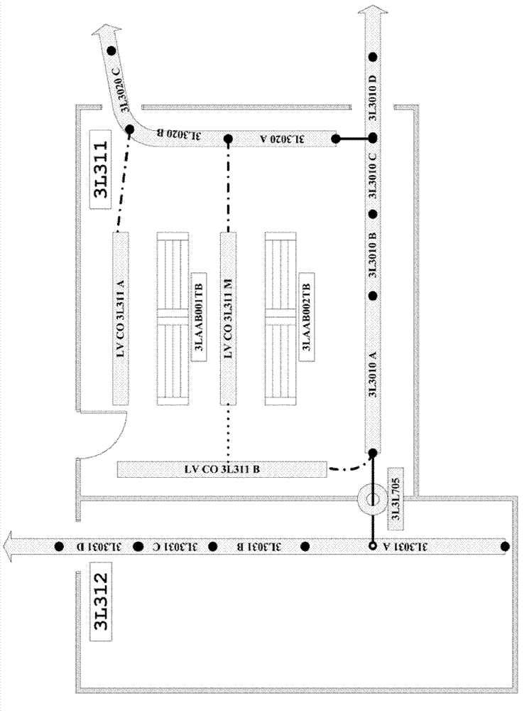
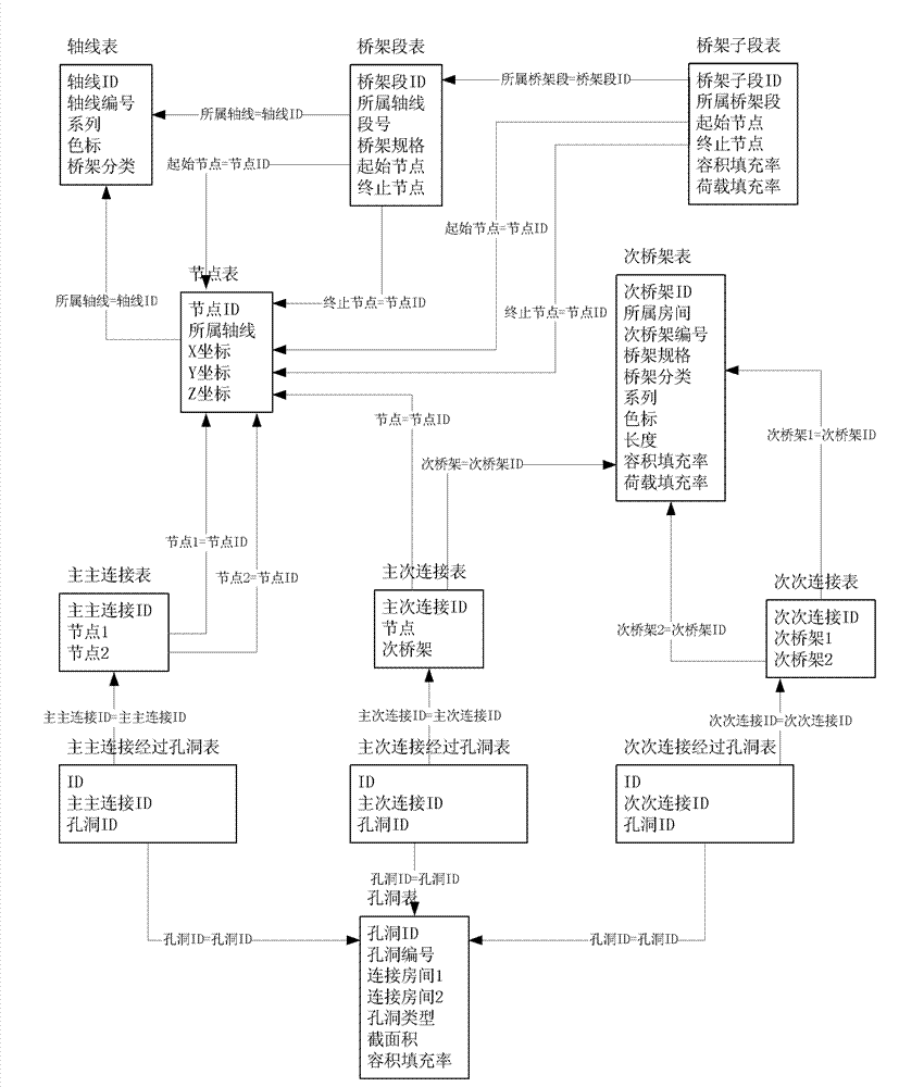
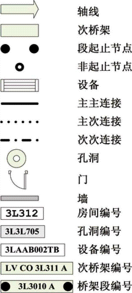
[0052]The method for constructing a cable tray network using a relational database provided by the present invention maps the actual cable tray system to the data elements in the computer system, so that the actual cable tray system appears in the computer as a system that will have a spatial position through the connection relationship A connected cable tray network is established by connecting the main bridge with the secondary bridge and holes without spatial location; wherein, the data elements include:

[0053] The main bridge frame refers to the main bridge frame whose position has been determined in the bridge system;

[0054] Axis refers to the first-floor main bridge located on the same unit, factory building and floor and arranged along the same path;

[0055] Nodes refer to some key points on the main bridge, and the spatial position and s...


PUM


Abstract

The invention relates to a design technology of a computer-aided cable laying path, in particular to a method for establishing a cable bridge network by using a relational database. The method comprises the following steps of: mapping an actual cable bridge system to be data elements in a computer system, thereby showing the actual cable bridge system as a communicated cable bridge network which is established by connecting a main bridge with spatial position and a secondary bridge and holes without spatial position through a connection relation in the computer; calculating a fill factor according to sections of the bridge; calculating a bridge load; and calculating fill factors of the holes. Through the method provided by the invention, the efficiency of computer-aided cable laying design work and design quality can be improved.

Description

technical field [0001] The invention relates to a computer-aided cable laying route design technology, in particular to a method for constructing a cable bridge network using a relational database. Background technique [0002] Cable laying line design is a complex and cumbersome task, especially for large-scale engineering construction projects such as nuclear power plants, where the system is complex, the safety level is high, and the amount of cable laying is large, so it is difficult to complete manually. With the wide application of computer-aided design in various fields, a new way of thinking is provided for the design of cable laying paths, which is to use computers to complete the design of cable laying paths. [0003] At present, there are three ways to use computer-aided cable laying path design: [0004] 1. Use commonly used office software such as spreadsheets to record, mainly relying on manual calculations. This type of method requires high personnel quality...

Claims


Application Information

Patent Timeline
Patent Type & Authority Patents(China)
IPC IPC(8): G06F17/50G06F17/30H02G3/00
Inventor 邓旭晨吕冬宝周晓斌丁洪波刘晓波黄耀
Owner CHINA NUCLEAR POWER ENG CO LTD
Why Eureka
Try Eureka