
System and method for detecting leakage of high-temperature gas in high-temperature high-pressure guide pipe of airplane

A high-temperature, high-pressure, high-temperature gas technology, applied in the field of high-temperature gas leakage detection systems, can solve the problems of false alarms of thermal insulation layers, complicated wiring, and difficulty in judging leakage, and achieve the effects of ensuring flight safety, improving dispatch rate, and high reliability.

Inactive Publication Date: 2012-06-06
NANJING UNIV OF AERONAUTICS & ASTRONAUTICS
View PDF0 Cites 5 Cited by
  • Summary
  • Abstract
  • Description
  • Claims
  • Application Information

AI Technical Summary

Problems solved by technology

Since the high-temperature gas conduit runs through the fuselage and wings of the aircraft, there are many parts that need to be monitored, so a large number of temperature sensors are arranged, making the wiring very complicated; In addition, the monitoring area of ​​the temperature sensor is related to the leak location and the size of the leak. It is very difficult to choose the layout location, and there are a large number of measurement blind spots.
(2) Pressure measurement method: by setting pressure sensors at different positions of the high-temperature gas conduit, and judging whether there is a leak by measuring the pressure change in the conduit, this measurement method can be used for the measurement of large leaks. For small leaks due to the working conditions of the environmental control system The pressure inside the conduit will fluctuate to a certain extent, coupled with the pneumatic hysteresis of pressure measurement, it is difficult to judge whether there is a leak
Although small leakage has little impact on the performance of the environmental control system, due to the high temperature of the gas, the damage caused by small leakage of the conduit to the surrounding system cannot be ignored
In addition, although the upstream leak can be determined by the downstream pressure change, it cannot accurately locate the specific location of the leak, and this measurement method also has shortcomings such as heavy weight

Method used


Image

  • System and method for detecting leakage of high-temperature gas in high-temperature high-pressure guide pipe of airplane
  • System and method for detecting leakage of high-temperature gas in high-temperature high-pressure guide pipe of airplane
  • System and method for detecting leakage of high-temperature gas in high-temperature high-pressure guide pipe of airplane

Examples


Embodiment Construction

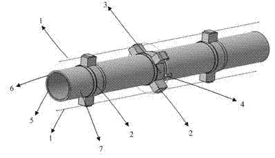
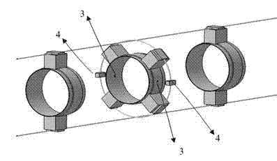
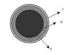
[0020] according to figure 1 As shown, the aircraft high-temperature gas conduit leakage detection system and method of the present invention are composed of two axial thermistor detection lines 1 , a wire mounting frame 2 , a diversion hole 3 and a temperature trigger 4 . The thermistor detection line 1 is divided into several detection units by using the lead mounting frame 2 . Each measuring unit is composed of a section of axial wire of line AB and a section of axial wire of line CD, and a circumferential thermistor detection loop connected in series between the sections. Each measuring unit is responsible for monitoring an area.

[0021] The thermal thermistor wire in the measurement unit has a high temperature coefficient of resistance. According to the relationship between resistance and temperature, it is divided into a positive temperature system thermistor and a negative temperature coefficient thermistor. The resistance of the former increases sharply with the incr...


PUM


Abstract

The invention provides a system and a method for detecting leakage of a high-temperature gas in a high-temperature high-pressure guide pipe of an airplane, and belongs to the field of high-temperature high-pressure gas leakage detection. The method is characterized by comprising the following processes that: (1) when the high-temperature gas is leaked from the guide pipe, the ambient temperature around the guide pipe is raised quickly; and due to the heating action of the gas, the resistance value of a thermistor is changed rapidly along the raising of the temperature so as to judge whether the gas is leaked; and (2) according to the theory, the variations of the resistance values of the ends AB, AD, CB, CD, AC and BD are detected at the same time; and if the resistance values of three ormore paths are different from the rated values, the gas in the area is leaked. Compared with other detection systems, the system has the advantages of simple structure, high reliability and the like,and can synchronously realize leakage judgment and position location of the high-temperature gas guide pipe of the air plane of other high-temperature gas pipelines. The leakage detection system has great significance for guaranteeing the flying safety and improving the running dispatch rate of the air plane.

Description

Technical field [0001] The invention relates to a high-temperature gas leakage detection system and method in an aircraft high-temperature and high-pressure conduit, belonging to the field of high-temperature gas leakage detection. Background technique [0002] Air management system is one of the important airborne equipment of the aircraft. Its function is to adjust the air for the cockpit and electronic equipment to meet its cooling, heating, pressurization and anti-icing requirements. It mainly includes bleed air, cabin pressure and temperature regulation, and air distribution. , engine and wing anti-icing subsystems, all systems are cross-linked through air ducts. Since the high-temperature and high-pressure gas flows in the duct, mechanical stress and thermal stress will be applied to the duct; at the same time, the connecting parts between the duct and the fuselage will also transmit the displacement and vibration caused by the change of the aircraft load distribution ...

Claims


Application Information

Patent Timeline
Patent Type & Authority Patents(China)
IPC IPC(8): G01M3/40G01K7/22G01K13/02G01K13/024
Inventor 蒋彦龙施红王瑜于磊徐雷李俊
Owner NANJING UNIV OF AERONAUTICS & ASTRONAUTICS
Learn More