Optical structure for improving output frequency of pulsed laser

A pulse laser and output frequency technology, applied in the laser field, can solve the problems of reducing the average power of laser pulses and increasing device loss, and achieve the effect of reducing single pulse energy and increasing pulse frequency

Active Publication Date: 2011-08-24
FUZHOU PHOTOP QPTICS CO LTD
View PDF5 Cites 2 Cited by
  • Summary
  • Abstract
  • Description
  • Claims
  • Application Information

AI Technical Summary

Problems solved by technology

This method not only has high requirements for the coating, but also the use of the beam combiner increases the loss of the device and reduces the average power of the laser pulse

Method used


Image

  • Optical structure for improving output frequency of pulsed laser
  • Optical structure for improving output frequency of pulsed laser
  • Optical structure for improving output frequency of pulsed laser

Examples


Embodiment Construction

[0014] The present invention will be further described below in conjunction with the drawings and specific embodiments.

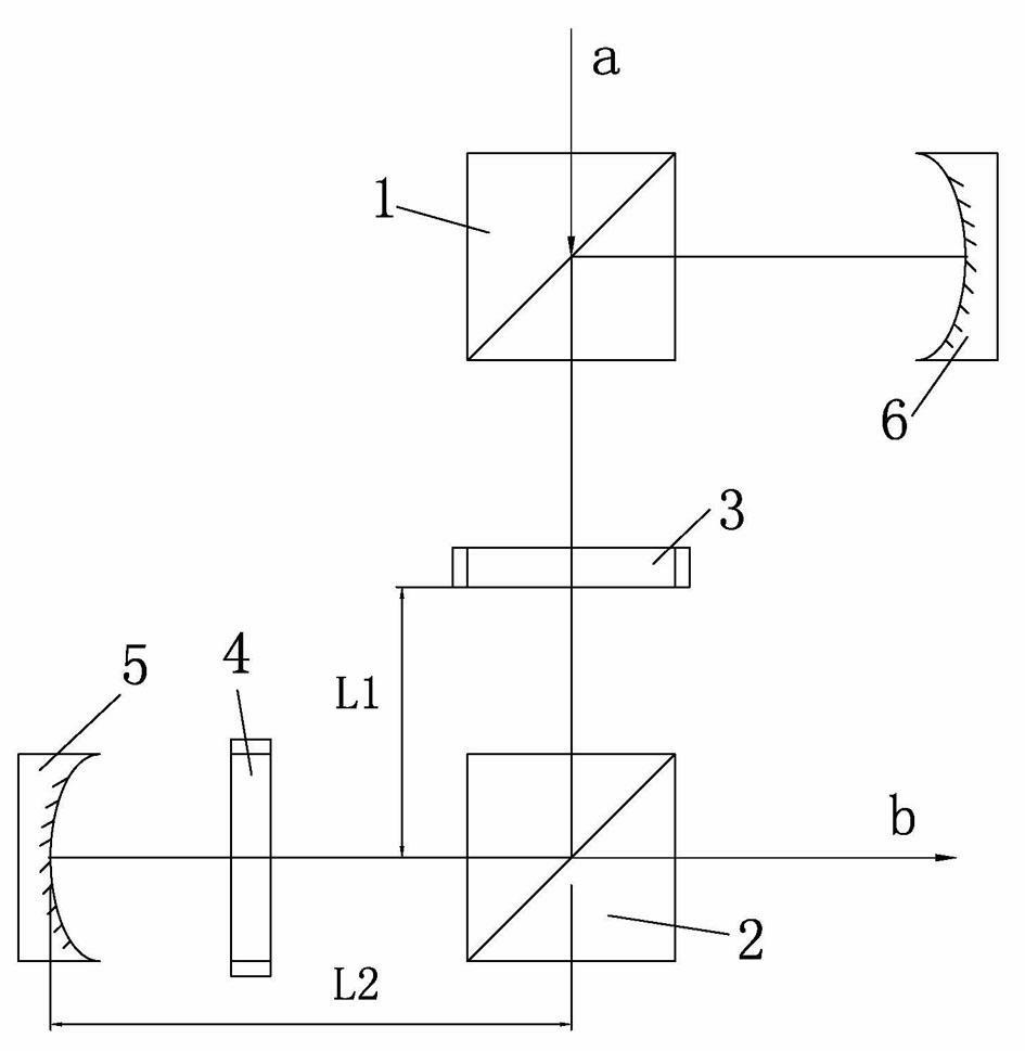
[0015] Such as figure 2 Shown is a specific embodiment of the present invention, an optical structure for increasing the output frequency of a pulsed laser, including two polarization beam splitting prisms (PBS): a first polarization beam splitting prism 1 and a second polarization beam splitting prism 2; two adjustable Wave plates: the first adjustable wave plate 3 and the second adjustable wave plate 4; two cavity mirrors: the first cavity mirror 5 and the second cavity mirror 6. The two tunable wave plates 3, 4 can be electro-optic crystals or magneto-optic crystals; the two cavity mirrors 5, 6 can be plano-concave cavity mirrors.

[0016] The working process is as follows. When the original pulsed laser a enters the optical structure through the first polarization beam splitter 1, the first tunable wave plate 3 is in the state of the λ / 2 wave plate, and wh...


PUM


Abstract

The invention discloses an optical structure for improving the output frequency of a pulsed laser. The optical structure comprises two polarization beam splitting (PBS) prisms, two tunable wave plates made of electro-optic crystals or magneto-optic crystals, and two cavity mirrors. An original pulsed laser beam is introduced to the cavity of the above optical structure by an electro-optical switch, and the laser output energy can be controlled by adjusting the waveform of the electro-optic wave plate or the magneto-optic wave plate at the rotation time so as to improve the output frequency ofthe pulsed laser and reduce the single-pulse energy without influencing the average power of the original pulse. The output new pulses are of the same sequence in the space.

Description

Technical field [0001] The invention relates to the field of laser technology, in particular to an optical structure for increasing the output frequency of a pulsed laser. Background technique [0002] Ultraviolet lasers have been successfully applied in the field of microelectronics manufacturing, such as the inspection of wafers and microcircuits. One advantage of UV light is that it can achieve high spatial resolution. In industrial applications, the average power of the ultraviolet laser is very important, and the output is proportional to the average power; while the high peak power is harmful to the application, it is easy to cause damage to the device. Therefore, continuous ultraviolet laser has become a choice of people. [0003] However, the ultraviolet laser is generally obtained by frequency conversion, and the non-linear frequency conversion efficiency of continuous light is very low. Therefore, to obtain continuous ultraviolet laser, a huge fundamental frequency opti...

Claims


Application Information

Patent Timeline
Patent Type & Authority Applications(China)
IPC IPC(8): G02F1/01G02F1/03G02F1/09
Inventor 吴砺任策林江铭
Owner FUZHOU PHOTOP QPTICS CO LTD
Why Eureka
Try Eureka