Unlock instant, AI-driven research and patent intelligence for your innovation.
Laser rapid processing method of ring groove in inner cavity of corrugated horn antenna
What is Al technical title?
Al technical title is built by PatSnap Al team. It summarizes the technical point description of the patent document.
A technology of corrugated horns and annular grooves, applied in metal processing equipment, laser welding equipment, manufacturing tools, etc., to achieve the effects of reducing single pulse energy, controlling area, and high precision
Active Publication Date: 2022-03-29
BEIJING UNIV OF TECH
View PDF19 Cites 0 Cited by
Summary
Abstract
Description
Claims
Application Information
AI Technical Summary
This helps you quickly interpret patents by identifying the three key elements:
Problems solved by technology
Method used
Benefits of technology
Problems solved by technology
Most of the existing research and patents focus on the structural design and manufacturing process optimization of the horn antenna, and the solution of using laser to improve the fine manufacturing level of the annular groove in the inner cavity has not been reported yet.
Method used
Image
Click on the blue label to locate the original text in one second.
Reading with bidirectional positioning of images and text.
Examples
Embodiment 1
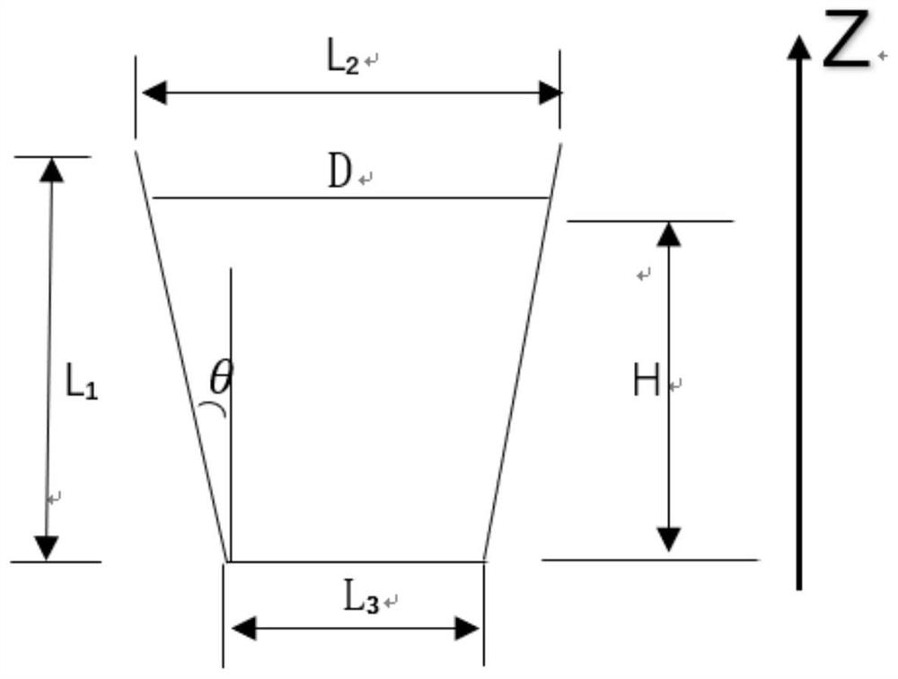
[0038] Embodiment one, such as image 3 As shown, when the tooth width t is each downward movement of the laser focus, the laser focus height H n for:
[0039] h n =H 0 -nt,n=0,1,2,... (3)
[0040] Ring groove diameter: D n =2(H 0-nt).tan14°+4,n=0,1,2,…(4)
[0041] where H 0 (H 0 ≤ L 1 ) is the starting height of the focal point, and n is the number of annular grooves.
[0042] In this embodiment, take H 0 =L 1 =10mm, at the same time design tooth width t=0.2mm, according to formula (3), focus height H 1 、H 2 、H 3 , ..., which are 9.8mm, 9.6mm, 9.4mm, ...; according to formula (4), the corresponding annular groove diameter D 1 、D 2 、D 3 , ..., followed by 7.9mm, 7.8mm, 7.7mm, ....
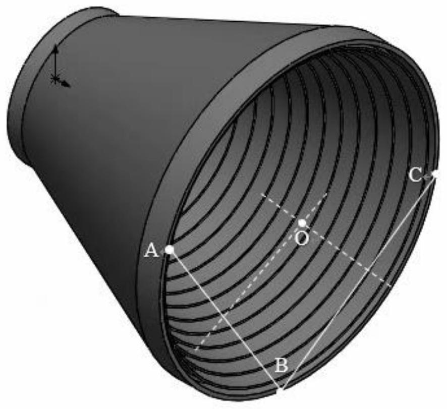
[0043] Using 532nm picosecond pulse laser, 2.5D scanning galvanometer, power 15W, scanning speed 250mm / s, repetition frequency 2500KHz, processing times 500 times. When processing the first groove, find point O through three-point positioning, and input focus height H 1 =9.8mm, ...
Embodiment 2
[0044] Embodiment two, such as image 3 As shown, when the tooth width t is each upward movement of the laser focus, the laser focus height H n for:
[0045] h n =H 0 +nt,n=0,1,2,... (5)
[0046] Ring groove diameter: D n =2(H 0 +nt).tan14°+4,n=0,1,2,…(6)
[0047] where H 0 (H 0 ≤ L 1 ) is the starting height of the focal point, and n is the number of annular grooves.
[0048] In this embodiment, take H 0 =3mm, at the same time design tooth width t=0.1mm, according to formula (5), focus height H 1 、H 2 、H 3 , ..., which are 3.1mm, 3.2mm, 3.3mm, ...; according to formula (6), the corresponding annular groove diameter D 1 、D 2 、D 3 , ..., followed by 5.55mm, 5.6mm, 5.65mm, ....
[0049] Using 532nm picosecond pulse laser, 2.5D scanning galvanometer, power of 15W, scanning speed of 250mm / s, repetition frequency of 3500KHz, and processing times of 500 times. When processing the first groove, find point O through three-point positioning, and input focus height H ...
PUM
Abstract
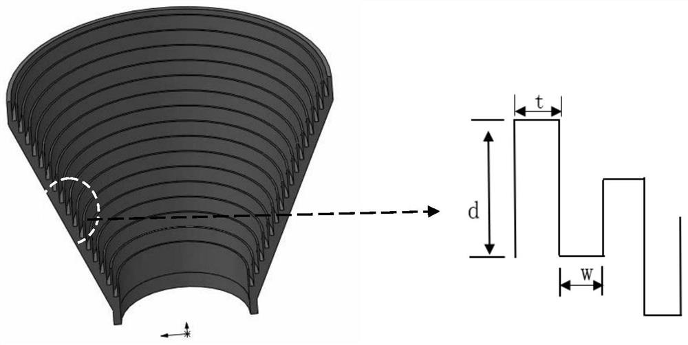
The invention relates to a laserrapid processing method for the ring groove of the inner cavity of the corrugated horn antenna. The method includes simplifying the ring groove of the inner cavity with a gradually changing diameter into a circular figure, and obtaining the circle diameter D from formulas (1) and (2). n , focus height H n ; Use the three-point positioning method to determine the center O on the central axis of the rotary part, so that the center of the laser-processed annular groove is parallel to the central axis of the hollow rotary part; after positioning the center O point, the programmed diameter is D n , the focus is H n The laser circular cutting track program controls the laser parameters to complete a circular groove processing along the antenna inner cavity according to the programmed circular cutting track; the tooth width t is used as the down / up movement of the laser focus, and the next circular groove is processed until the processing Produce n circular grooves. The invention has low restrictions on the opening angle of the rotary parts, and can be applied to the processing of inner cavity wall grooves of hollow rotary parts such as corrugated horns with equal diameters and positive and negative opening angles. Shorter and cheaper.
Description
technical field [0001] The invention relates to the processing technology of annular grooves in the inner cavity of corrugated horn antennas, in particular to a method for processing axially distributed annular grooves in the inner cavity of a rotary part by utilizing the characteristics of high laser energy density, non-contact processing and good stability . Background technique [0002] As a modern precision processing technology, laser has the advantages of non-contact, high energy density, and direct material removal during processing, which avoids damage to workpieces caused by cutting forces during mechanical processing, and at the same time, the micron-level spot diameter ensures micro-milling. Precision, more and more widely used in micro-milling, micro-grooving and other fields. However, limited by factors such as laser power, focal depth, and energy absorption rate, the groove depth of materials is still limited, and new solutions are still needed. At present, f...
Claims
Application Information
Patent Timeline
Application Date:The date an application was filed.
Publication Date:The date a patent or application was officially published.
First Publication Date:The earliest publication date of a patent with the same application number.
Issue Date:Publication date of the patent grant document.
PCT Entry Date:The Entry date of PCT National Phase.
Estimated Expiry Date:The statutory expiry date of a patent right according to the Patent Law, and it is the longest term of protection that the patent right can achieve without the termination of the patent right due to other reasons(Term extension factor has been taken into account ).
Invalid Date:Actual expiry date is based on effective date or publication date of legal transaction data of invalid patent.

