Intelligent power supply control system and control method thereof

A control system and intelligent power supply technology, applied in the direction of electrical program control, comprehensive factory control, comprehensive factory control, etc., can solve the problems of air conditioner opening, power waste, etc., and achieve the effect of automatically starting or disconnecting the load power supply

Inactive Publication Date: 2011-08-24
WENZHOU MTLC ELECTRIC APPLIANCES
View PDF5 Cites 3 Cited by
  • Summary
  • Abstract
  • Description
  • Claims
  • Application Information

AI Technical Summary

Problems solved by technology

[0002] The traditional room power supply system is basically a manual control system. For example, the startup and shutdown of the air conditioner and the startup and shutdown of the lighting are all manually operated by the user in the room, so it often happens that the lighting and air conditioning are turned on when there is no one in the room. phenomenon, resulting in a serious waste of electricity

Method used


Image

  • Intelligent power supply control system and control method thereof
  • Intelligent power supply control system and control method thereof

Examples


Embodiment 1

[0018] (Embodiment 1, intelligent power supply control system)

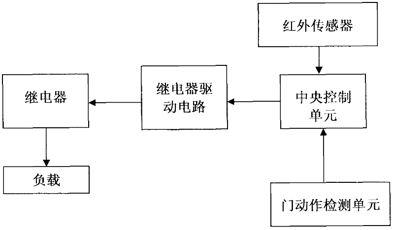
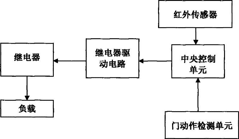
[0019] See figure 1 , the intelligent power supply control system of this embodiment includes: a relay drive circuit, a relay connected to the control output end of the relay drive circuit, a controlled load circuit controlled on and off by the relay, and a central control circuit connected to the control input end of the relay drive circuit. A control unit, an infrared sensor connected to the central control unit for conducting the controlled load circuit when an infrared movement signal is detected, and a door action monitoring unit connected to the central control unit.

[0020] The door action monitoring unit is a monitoring circuit including a micro switch, or a monitoring circuit including an infrared sensor.

[0021] The controlled load circuit includes an AC lighting circuit, an air conditioner power circuit and a DC circuit.

[0022] The system also includes a remote host, the output end of the central...

Embodiment 2

[0024] (Embodiment 2, intelligent power supply control system)

[0025] As another implementation manner, the infrared sensor and the door action monitoring unit transmit monitoring information with the central control unit in a wireless manner.

Embodiment 3

[0026] (Embodiment 3, control method)

[0027] This embodiment is the control method of Embodiment 1. When the infrared sensor detects that there is an infrared mobile signal in the room, the central control unit controls the relay through the relay drive circuit to conduct the controlled load circuit;

[0028] When the door action monitoring unit detects a door opening or closing action, and the infrared sensor detects that there is no infrared movement signal in the room within 30 seconds to 10 minutes, that is, when no infrared movement signal is detected, the central control unit drives the circuit through the relay The control relay disconnects the controlled load circuit.


PUM


Abstract

The invention discloses an intelligent power supply control system and an intelligent power supply control method. The control system comprises a relay driving circuit, a relay, a controlled loading loop, a central control unit, an infrared sensor and a door movement monitoring unit, wherein the relay is connected with a control output end of the relay driving circuit; the ON/OFF of the controlled loading loop is controlled by the relay; the central control unit is connected with a control input end of the relay driving circuit; and the infrared sensor is used for the central control unit to control the ON/OFF of the controlled loading loop when an infrared mobile signal is monitored. The control method comprises the following steps that: the infrared sensor monitors that the infrared mobile signal exists in the room, the central control unit controls the relay to conduct the controlled loading loop through the relay driving circuit; and when the door movement monitoring unit monitors the door open or close action, and the infrared sensor monitors that the infrared mobile signal does not exist in the room in the preset time, the central control unit controls the relay to cut off the controlled loading loop through the relay driving circuit so as to realize automatic starting or cutting off of a load power.

Description

technical field [0001] The invention relates to the technical field of indoor power supply control, in particular to an intelligent power supply control system and a control method thereof. Background technique [0002] The traditional room power supply system is basically a manual control system. For example, the startup and shutdown of the air conditioner and the startup and shutdown of the lighting are all manually operated by the user in the room, so it often happens that the lighting and air conditioning are turned on when there is no one in the room. phenomenon, resulting in a serious waste of electricity. Contents of the invention [0003] The purpose of the present invention is to provide an intelligent power supply control system capable of automatically starting or disconnecting the load power supply. [0004] Another object of the present invention is to provide a control method for the above intelligent power supply control system. [0005] The technical solu...

Claims


Application Information

Patent Timeline
Patent Type & Authority Applications(China)
IPC IPC(8): G05B19/418
CPCY02P90/02
Inventor 陈福华
Owner WENZHOU MTLC ELECTRIC APPLIANCES
Why Eureka
Try Eureka