Combined vehicle brake system with hydraulically and electromechanically actuatable wheel brakes

A technology for vehicle braking and hydraulic actuation, which is applied in the directions of brakes, brake transmission devices, vehicle components, etc., to achieve the effect of cost reduction and cost avoidance

Active Publication Date: 2011-08-24
CONTINENTAL AUTOMOTIVE TECH GMBH
View PDF9 Cites 26 Cited by
  • Summary
  • Abstract
  • Description
  • Claims
  • Application Information

AI Technical Summary

Problems solved by technology

A disadvantage of the braking system described above is that the hydraulic brakes on the front wheels usually have to be configured as vacuum-assisted in order to obtain sufficient hydraulic brake pressure

Method used


Image

  • Combined vehicle brake system with hydraulically and electromechanically actuatable wheel brakes
  • Combined vehicle brake system with hydraulically and electromechanically actuatable wheel brakes
  • Combined vehicle brake system with hydraulically and electromechanically actuatable wheel brakes

Examples


Embodiment Construction

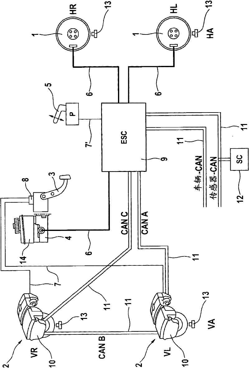
[0034] figure 1 A circuit diagram of a first exemplary embodiment of the vehicle braking system according to the invention is schematically shown. The braking system according to the example comprises two electromechanical brake actuators 2 on the front axle VA (VR: front right, VL front left) and individual brake actuators 2 on the wheels of the rear axle HA (HR: rear right, HL: rear left). One hydraulic wheel brake 1 , the electromechanical brake actuators each act on a disc brake, for example. Rear wheel brake 1 is designed in such a way that normal braking can be performed without additional “hydraulic” assistance by means of the usual driver's depressing force introduced by brake pedal 3 .

[0035] According to this example, hydraulic wheel brake 1 is designed as a drum brake, which is acted upon with hydraulic pressure via signal master brake cylinder 4 without any vacuum boost.

[0036] The hydraulic brake pressure for the hydraulically actuatable wheel brakes 1 is pr...


PUM


Abstract

Combined vehicle braking system, in particular for motor vehicles, comprising an electromechanical service brake system for a first axle of the vehicle, said electromechanical brake system comprising at least one electromechanically actuatable wheel brake (2), and comprising a hydraulic service brake system for a second axle of the vehicle, said hydraulic brake system comprising a main brake cylinder (4) and at least one hydraulically actuatable wheel brake (1), wherein the first axle is a front axle (FA) and the second axle is a rear axle (RA).

Description

technical field [0001] The invention relates to a hydraulic and electromechanical hybrid vehicle braking system according to the preamble of claim 1 . The vehicle braking system is used in motor vehicles, in particular in automobiles. Background technique [0002] Electromechanical brakes are known in which the wheel brakes can be actuated directly electromechanically, for example by means of an electric motor. DE 196 15 186 C1 describes a brake system in which an electric motor with a rotor is assigned to each wheel brake. When the motor is driven, the rotational movement of the rotor is converted into a translational movement by means of a lead screw. The axial force is multiplied by a mechanical transmission designed as a lever mechanism and transmitted to a piston, which presses the brake lining against the brake disc and generates a braking torque. It has been proposed that all (four) wheels of the vehicle be equipped with such electromechanical wheel brakes. The di...

Claims


Application Information

Patent Timeline
Patent Type & Authority Applications(China)
IPC IPC(8): B60T13/58B60T13/74
CPCB60T13/745B60T13/588B60T13/746B60T8/267B60T13/58B60T13/74
Inventor P·林霍夫A·海泽
Owner CONTINENTAL AUTOMOTIVE TECH GMBH
Why Eureka
Try Eureka