Electrical control variable plunger pump and pump control hydraulic system thereof

A technology of variable plunger and plunger pump, which is applied in the direction of fluid pressure actuated system components, pump control, liquid variable capacity machinery, etc. It can solve the problem of insufficient load driving force, difficulty in quick response, and slow response of variable frequency variable speed system and other issues, to achieve fine control of flow output and pressure output, improve efficiency and control accuracy, and achieve flexible composition and layout.

Inactive Publication Date: 2011-08-31
许宏
View PDF6 Cites 11 Cited by
  • Summary
  • Abstract
  • Description
  • Claims
  • Application Information

AI Technical Summary

Problems solved by technology

The low efficiency of the hydraulic system, high energy consumption, and high heat generation are essentially caused by excess flow. Unnecessary flow must be discharged, resulting in leakage loss and overflow loss. When the required flow cannot be met (excess flow is negative), it will cause insufficient load driving force, power drop, and cavitation may occur
[0010] The existing pump control systems of variable displacement plunger pumps, variable vane pumps or other variable pumps all rely on variable mechanisms to respond to instantaneous changes in the flow demand of the system, and it is very

Method used


Image

  • Electrical control variable plunger pump and pump control hydraulic system thereof
  • Electrical control variable plunger pump and pump control hydraulic system thereof
  • Electrical control variable plunger pump and pump control hydraulic system thereof

Examples


Embodiment Construction

[0080] The present invention will be further described below in conjunction with the accompanying drawings.

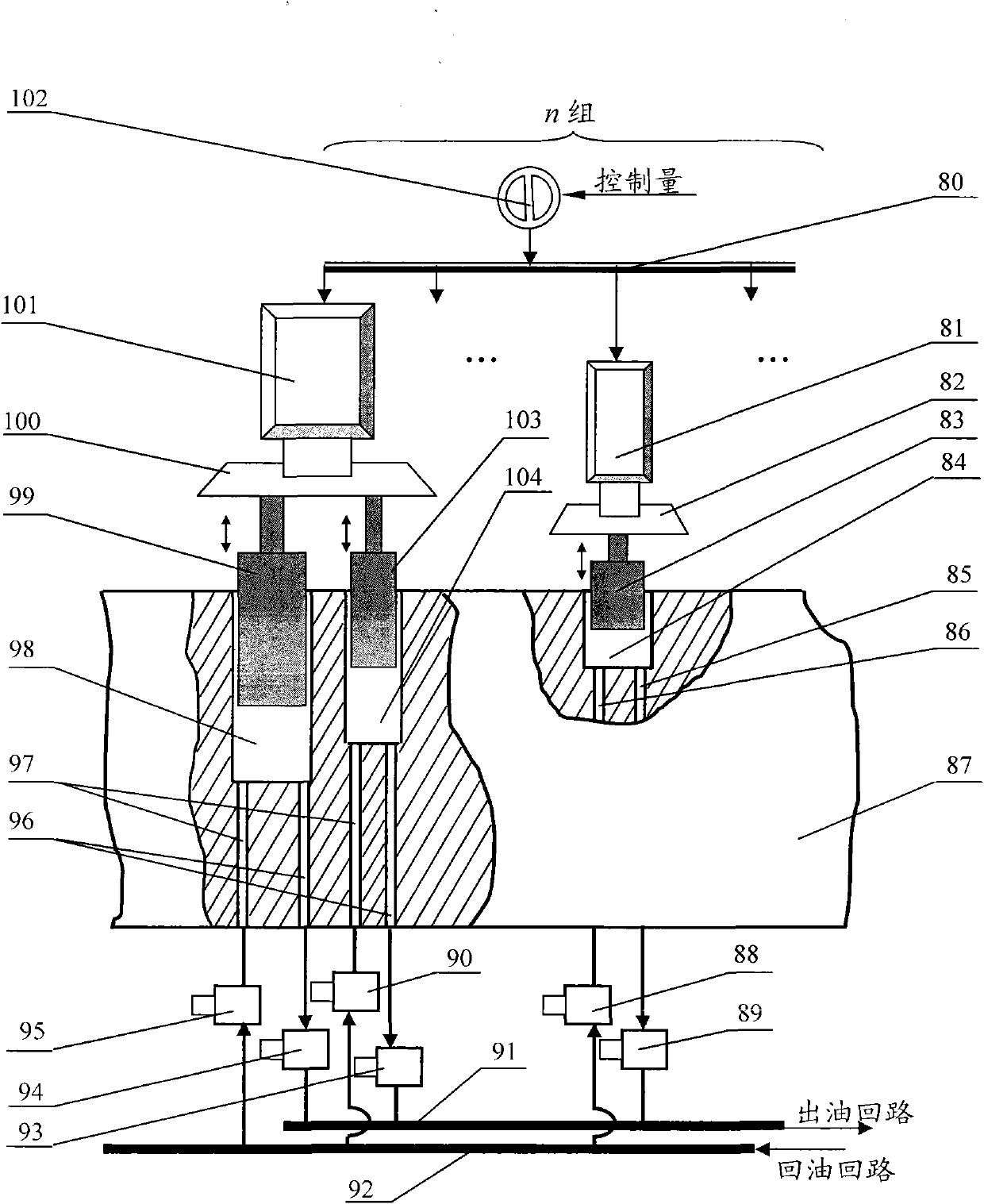
[0081] in the attached figure 1 In , a schematic diagram of the structure of an electronically controlled variable displacement pump is given. The text "n group" in the figure means that there are n plunger groups in a pump (a natural number of n≥2), and the ellipsis in the figure indicates other plunger groups of the n groups of plunger groups that are not shown in the figure. There are two sets of plunger sets, one set of two plungers and one set of one plunger.

[0082] attached figure 1 The electric device 101 of one plunger group is connected to one end of the corresponding mechanical connection device 100 , and the other end of the mechanical connection device 100 is connected to one end of the two plungers 99 , 103 . The plunger hole on the plunger 99, the plunger 103 and the corresponding cylinder block 87, and the oil inlet passage 97, the oil outlet passag...


PUM


Abstract

The invention discloses an electrical control variable plunger pump which is composed of a driver (102), electric actuators (101,81), mechanical connecting devices (100, 82), n groups of plunger groups, a cylinder body (87), oil inlet channels (97, 88), oil outlet channels (96, 85); oil inlet valves (88, 90, 95) and oil outlet valves (89, 93, 94), and a pump control system can be formed by matching a controller, an executing mechanism, a feedback system and a loading object; the controller generates control amount according to received external instructions, feedback information and built-in control algorithm; the driver changes the driving current and voltage of the electric actuators according to the control amount; the electric actuators drive the plunger groups to perform the corresponding linear movement to finish the oil intake and oil exhaust through the mechanical connecting devices, the instant displacement of the pump follows the changes of the external instructions, and the control of motion parameters and process changes of the loading object is realized; and the whole pump control system has the advantages of simple structure, rapid response and flexible control strategy.

Description

technical field [0001] The hydraulic system is a fluid power transmission system, which is widely used in various aspects of the industrial field, and the power device of the hydraulic system is its key component, which largely determines the static and dynamic characteristics of the system. The present invention proposes a new type of variable displacement pump and a pump control system using the pump, especially an electronically controlled variable displacement plunger pump and the pump control system for the power device of the hydraulic system. Background technique [0002] The power unit in the existing hydraulic system is mainly a hydraulic pump, which is driven by a prime mover, converts the input electric energy or mechanical energy into hydraulic energy, and delivers it to the system in the form of pressure and flow. Hydraulic pumps are generally driven by (rotating) electric motors, and are also driven by other power machinery (diesel engines, gasoline engines, ga...

Claims


Application Information

Patent Timeline
IPC IPC(8): F04B49/06F15B21/08
Inventor 许宏
Owner 许宏
Why Eureka
Try Eureka