Electronic control P step mechanism for electric vehicle

An electric vehicle and electric control technology, applied in transmission control, mechanical equipment, components with teeth, etc., can solve problems such as poor reliability

Inactive Publication Date: 2011-08-31
李金东
View PDF5 Cites 21 Cited by
  • Summary
  • Abstract
  • Description
  • Claims
  • Application Information

AI Technical Summary

Problems solved by technology

[0003] The purpose of the present invention is to provide an electronically controlled P gear mechanism for electric vehicles

Method used


Image

  • Electronic control P step mechanism for electric vehicle
  • Electronic control P step mechanism for electric vehicle
  • Electronic control P step mechanism for electric vehicle

Examples


Embodiment Construction

[0014] The present invention will be described in detail below in conjunction with the accompanying drawings and with the best embodiment.

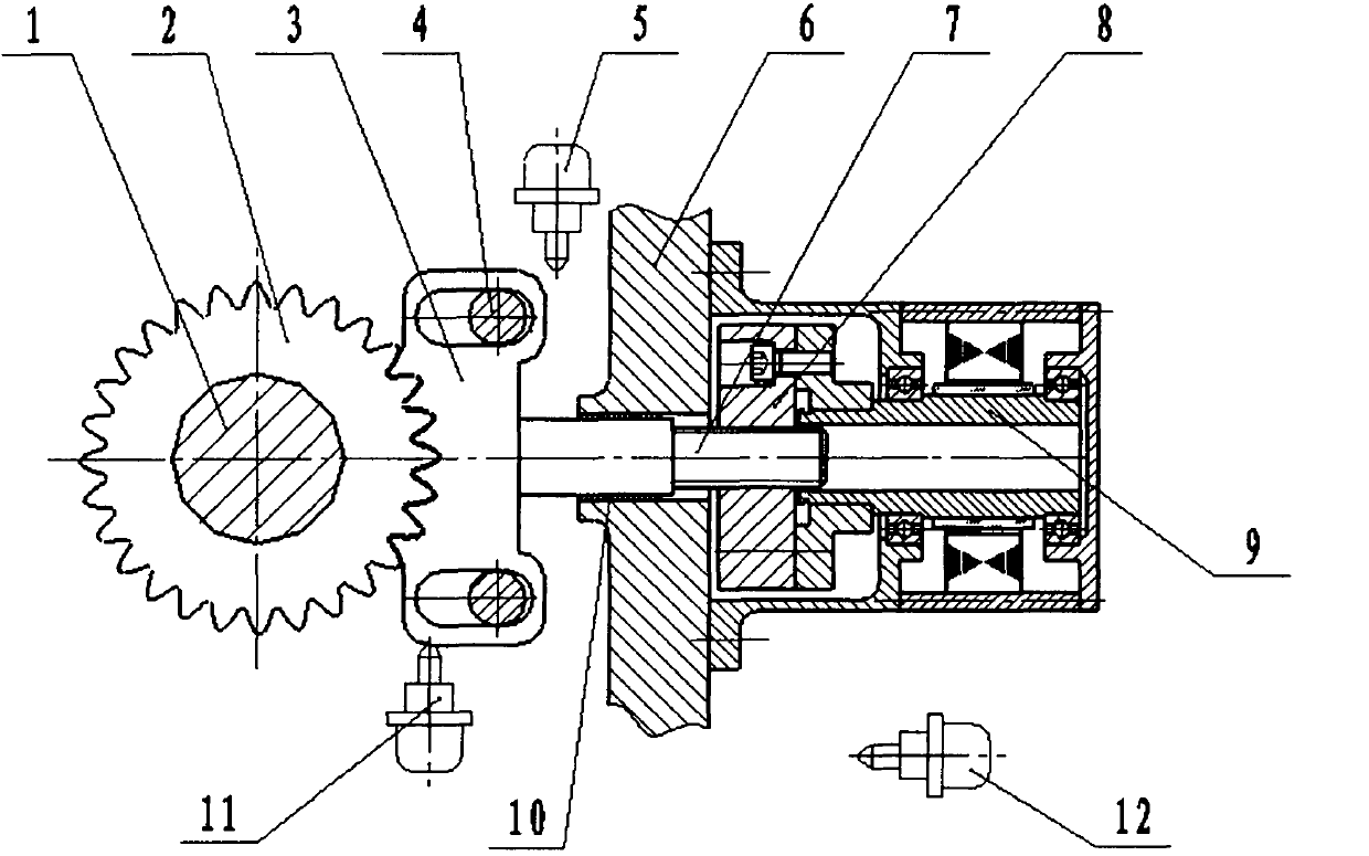
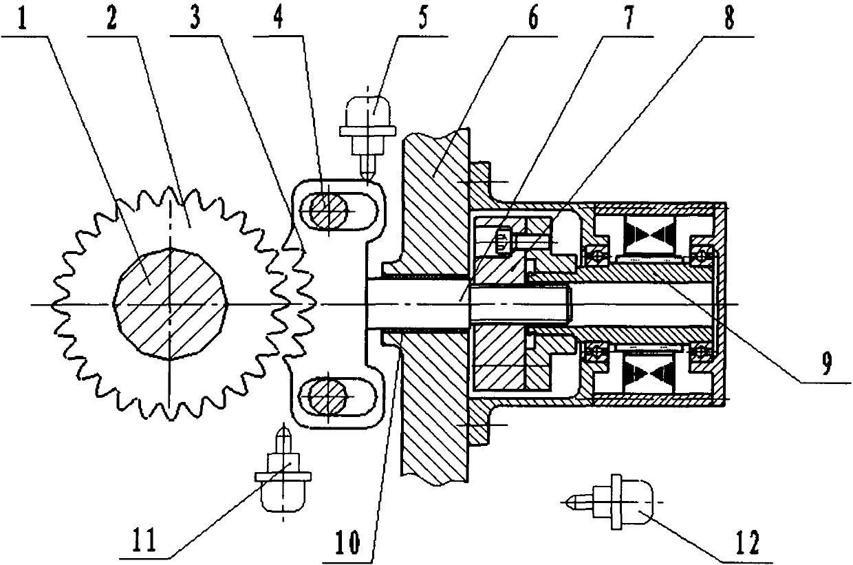
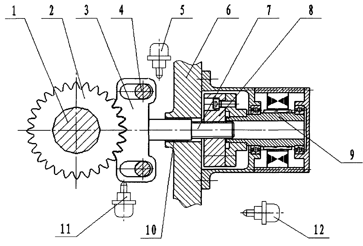
[0015] refer to Figure 1-Figure 2 , the electronically controlled P gear mechanism for electric vehicles of the present invention consists of a gear shaft (1), a locking wheel (2), a locking pawl (3), a support pin (4), a release signal switch (5), a box Body (6), pull rod (7), nut (8), power motor (9), axle sleeve (10), lock signal switch (11) and P block signal switch (12);

[0016] The locking claw (3) has teeth corresponding to the tooth shape of the locking wheel (2), and the locking wheel (2) is fixed on the gear shaft (1) of the reducer;

[0017] There is a waist-shaped through hole on the locking claw (3), and a support pin (4) is arranged in the through hole, and a clearance fit is formed between them, and the support pin (4) is fixedly installed on the box body (6);

[0018] The locking claw (3) and the pull rod (7) are fixed...


PUM


Abstract

The invention discloses an electronic control P step mechanism for an electric vehicle, and relates to an electronic control locking mechanism for parking of the electric vehicle. A locking claw is provided with teeth which are corresponding with the tooth shape of a locking wheel, and the locking wheel is fixed on a gear shaft of a speed reducer; a waist-shaped through hole on the locking claw is provided with a supporting pin shaft; the locking claw and a pulling rod are fixed together to form an assembly member; the pulling rod is the support of a shaft sleeve in a box body hole, and the pulling rod and the shaft sleeve form clearance fit; the screw part on the pulling rod and a nut form a spiral motion pair, and the rotation motion of the nut is converted into the axial motion of the pulling rod; a dynamic motor is fixed on a box body, and an output shaft of the dynamic motor and the nut are fixedly connected; a loosen signal switch and a locking signal switch form a signal feedback system of the moving position of the locking claw; and a P step signal switch is installed at a gear engaging position of the vehicle. By the electronic control P step mechanism provided by the invention, the problem that the exiting electric vehicle only depends on hands to brake, and the reliability performance is poor is solved.

Description

technical field [0001] The invention relates to an electric control locking mechanism for electric vehicle parking. Background technique [0002] At present, as a new energy vehicle, electric vehicles will gradually become the primary vehicle of choice for people due to their many advantages such as energy saving and emission reduction, simple maintenance, and easy driving. However, when the current electric vehicle is parked, it can only be parked at the site by pulling the hand brake, and only the hand brake is used to park the vehicle at the site. Its reliability and safety have been questioned by users. Using electric energy to realize the electronically controlled parking (P block) locking mechanism on the gearbox has become the research object of many scientific and technological workers. Contents of the invention [0003] The purpose of the present invention is to provide an electronically controlled P-gear mechanism for electric vehicles. The present invention sol...

Claims


Application Information

Patent Timeline
IPC IPC(8): F16H63/34
Inventor 李金东
Owner 李金东
Why Eureka
Try Eureka