Capacity testing method

A technology of capacitance testing and capacitance, which is applied in the direction of measuring devices, measuring electrical variables, measuring resistance/reactance/impedance, etc., can solve the problems of capacitance value error and test accuracy reduction, and achieve the effect of low cost and convenient implementation

Inactive Publication Date: 2011-08-31
SHANGHAI RES INST OF MICROELECTRONICS SHRIME PEKING UNIV
View PDF4 Cites 6 Cited by
  • Summary
  • Abstract
  • Description
  • Claims
  • Application Information

AI Technical Summary

Problems solved by technology

[0005] For example, if you want to test the interlayer capacitance C between the third layer interconnection line and the fourth layer interconnection line 43 (See figure 1 ), you can connect one port of the test machine test terminal to the interconnection line a 32, apply the H test signal to it, connect the other port to the interconnection line b 42, apply the L test signal to it, and then test the two The capacitance value between the two ports is taken as the interlayer capacitance C 43 capacitance value, but in this test scheme, because other interconnection lines outside the interconnection line a 32 and the interconnection line b 42 are in a floating state, when there are signals on the interconnection line a 32 and the interconnection line b 42, these The suspended interconnection wires will induce charges to the two signal-applied interconnection wires (i.e. interconnection line a 32 and interconnection line b 42 ), generating parasitic capacitance, so that the measured capacitance value of the testing machine includes no These expected parasitic capacitances cause large errors in the measured capacitance values, resulting in reduced test accuracy

Method used


Image

  • Capacity testing method
  • Capacity testing method
  • Capacity testing method

Examples


no. 1 example

[0020] The first embodiment, a single test.

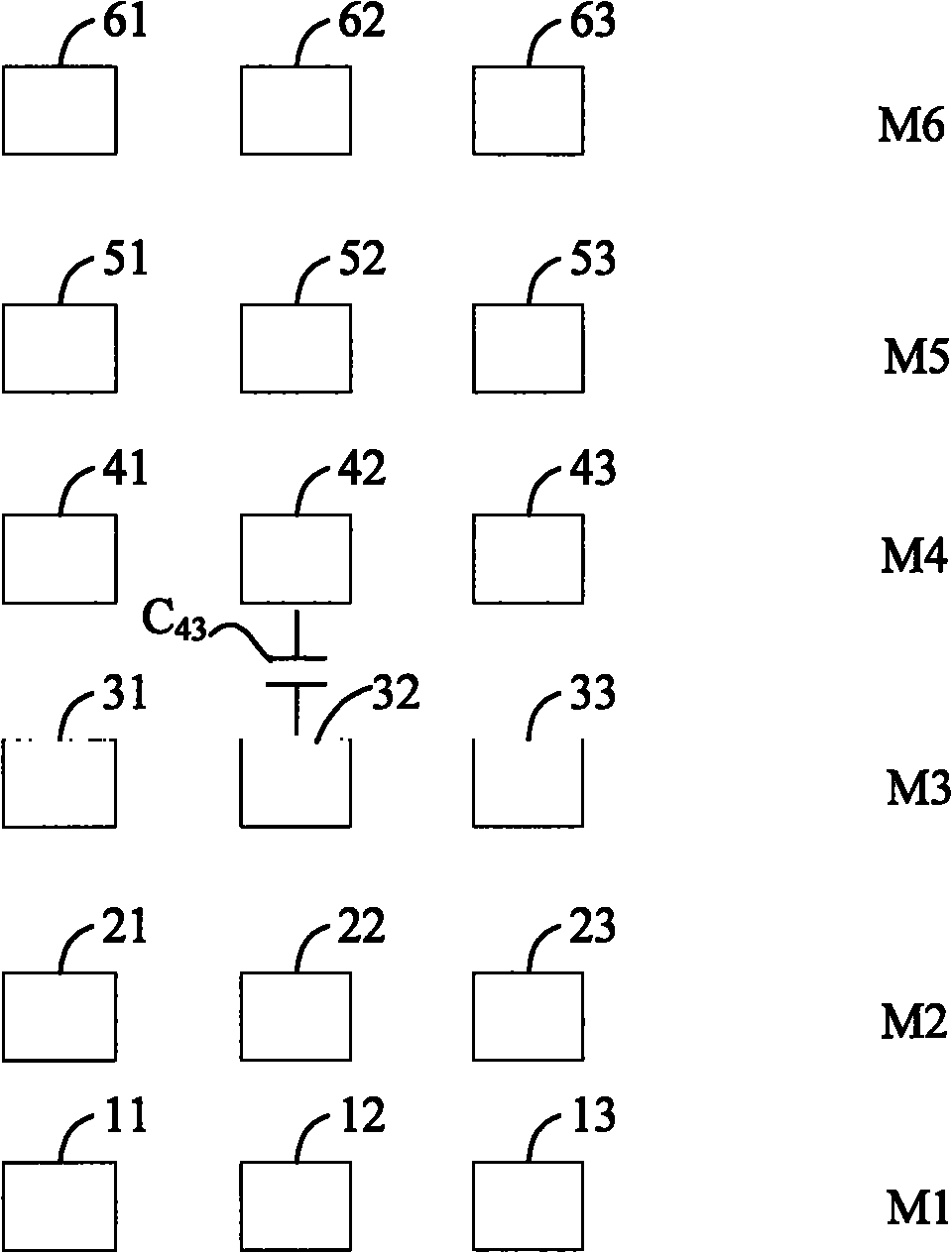
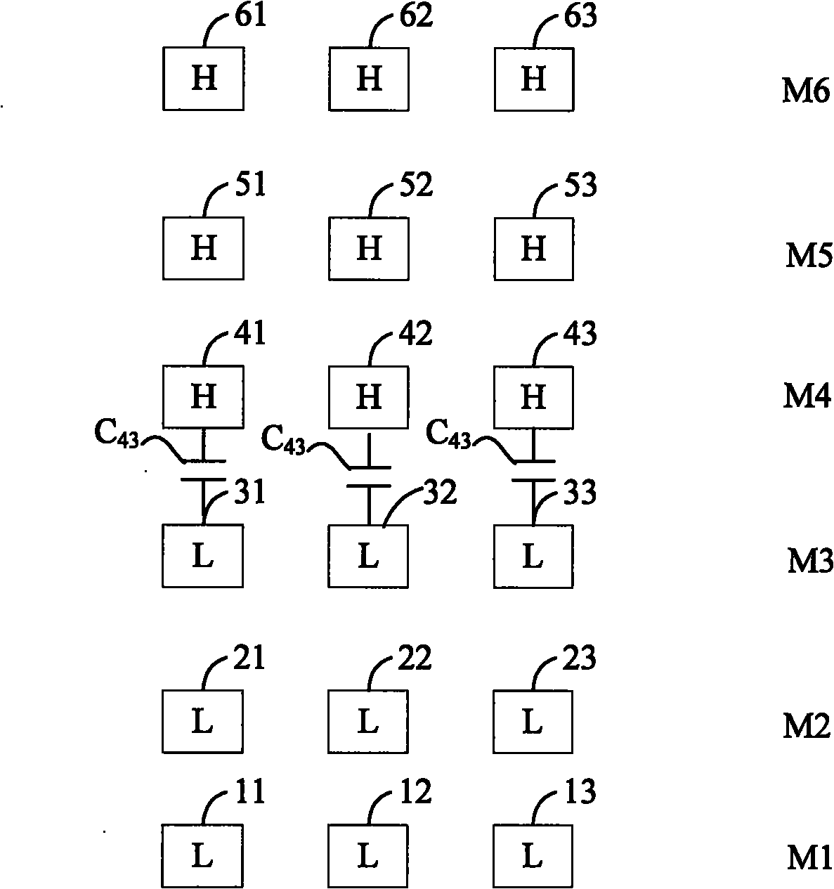
[0021] Reference figure 2 , To test the interlayer capacitance C between M3 and M4 43 As an example, the specific test process is:

[0022] Divide the original test signal H output by the capacitance testing machine into 6 branches, and each branch outputs a signal H; then apply the signals H output from the 6 branches to the interconnection line b42, interconnection line c41, and interconnection line d52. , The interconnection line e51, the interconnection line f62, and the interconnection line g61, because the interconnection line h43, the interconnection line i53, and the interconnection line j63 are connected to the interconnection line c41, the interconnection line e51, and the interconnection line g61, respectively, A signal H is also applied to the interconnection line c41, the interconnection line e51, and the interconnection line g61, and the signal H is applied to the interconnection line c41 to the interconnection line j63; ...

no. 2 example

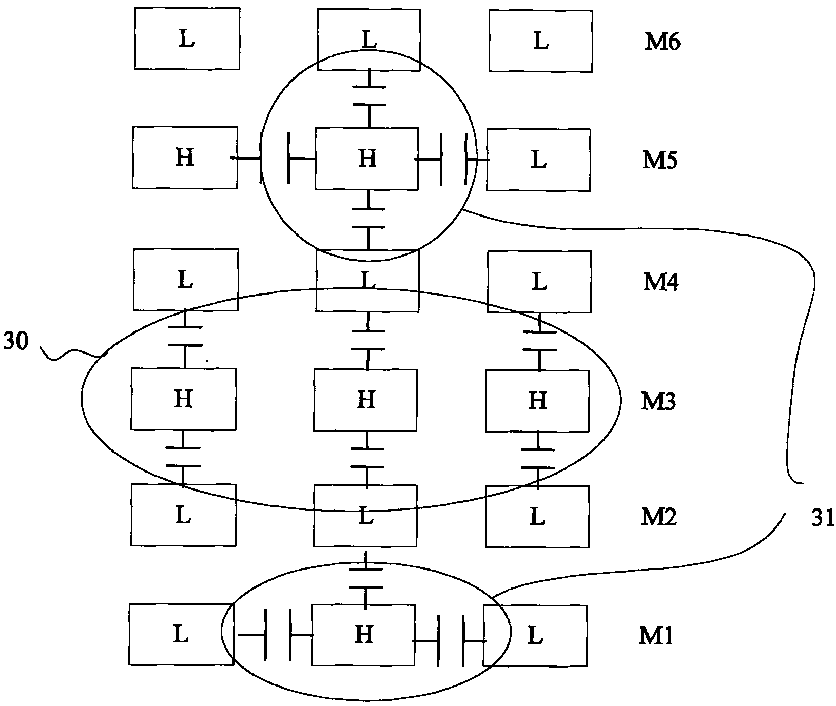
[0026] The second embodiment is tested multiple times.

[0027] In order to save the test chip area, in some cases, not all interconnect lines use independent pads. For some special needs, the pads may be shared, that is, some interconnect lines are connected to a pad through the pad When a signal is applied to the interconnection line, the signal is applied to all the interconnection lines connected to the pad at the same time. In this case, it is especially necessary to adopt multiple test schemes, pass multiple tests, and further calculate the capacitance to be measured, and perform multiple tests. It is not limited to the case where pads are shared. For the case where pads are not shared, multiple test schemes can also be applied.

[0028] Hypothesis figure 2 The interconnection line p11 and interconnection line s13 are connected to pad1, the interconnection line m22 is connected to pad2, the interconnection line k31 and the interconnection line q33 are connected to pad3, the ...


PUM


Abstract

The invention discloses a capacity testing method in a multi-layer interconnection system which is used for increasing the accuracy of capacity test. The method comprises the following steps: according to a test signal applying manner, applying test signals to all interconnected wires in the multi-layer interconnection system; after applying the test signals each time, testing the overall capacity value of the multi-layer interconnection system; and calculating a to-be-tested capacity value, according to the tested overall capacity value and the quantitative relation between the overall capacity value and the to-be-tested capacity value.

Description

Technical field [0001] The invention relates to the field of semiconductors, and in particular to a capacitance testing method in a multilayer interconnection line system. Background technique [0002] With the development of integrated circuit technology, the number of interconnection lines on the same chip has become more and more, from three layers and four layers to nine layers and ten layers or more. What follows is that the interconnection delay gradually becomes an influence The bottleneck of integrated circuit development. Since interconnection line parasitic parameters such as interconnection capacitance and interconnection resistance have a decisive influence on interconnection delay, the test of interconnection line parasitic parameters has attracted increasing attention. [0003] At present, the test machines for capacitance testing in the industry are based on the principle of bridge measurement. There are only two ports on the test end of the machine, which output hi...

Claims


Application Information

Patent Timeline
Patent Type & Authority Applications(China)
IPC IPC(8): G01R27/26
Inventor 秦晓静蒋乐乐程玉华
Owner SHANGHAI RES INST OF MICROELECTRONICS SHRIME PEKING UNIV
Why Eureka
Try Eureka