

Online analysis and early warning method for low-frequency oscillation of electric power system
A low-frequency oscillation and power system technology, applied to electrical components, circuit devices, AC network circuits, etc., can solve the problems of difficult to distinguish the change law of the carrier signal at the symbol flip point, large processing errors, complex calculations, etc., to achieve rapid response capability And robustness, calculation accuracy, avoiding the effect of integral operation
- Summary
- Abstract
- Description
- Claims
- Application Information
AI Technical Summary
Problems solved by technology
Method used
Image

Examples
Embodiment 1
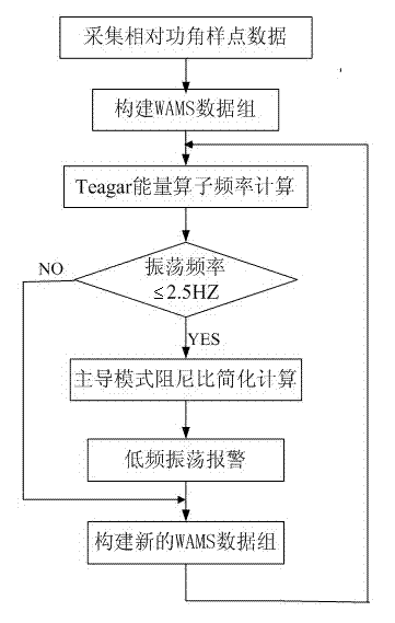
[0042]An on-line analysis and early warning method of low-frequency oscillation in a power system, the method comprising the following steps:
[0043] a. The relative power angle is collected from the phase angle measurement unit (PMU) of the UHV synchronous power grid wide-area measurement system, and the relative power angle and the time of collecting the relative power angle are taken as a sample point data to Acquire sample point data for the sampling frequency where 8 Hz ≤ ≤15Hz;
[0044] b. According to the chronological order of the sample data, N sample data are continuously taken, and the N sample data constitute a WAMS data group, among which 150≤N≤2000;
[0045] c. Perform k-point median filtering or k-point mean filtering on the WAMS data set, where 3≤k≤9, and the filtered relative power angle signal is recorded as ;
[0046] d. Use Teagar energy operator to process relative power angle signal :
[0047] d1. Calculate the relative power angle signal The...
Embodiment 2
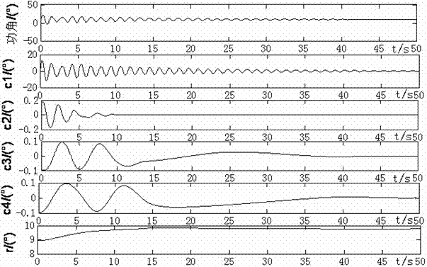
[0069] An on-line analysis and early warning method of low-frequency oscillation in a power system, the steps of which are the same as those in Embodiment 1, taking the relative power angle signal of No. 7 unit relative to No. 1 unit in the 8-unit system in the PSASP as an example, wherein in step a, Pick =15Hz, take N=150 in step b, take k=7 in step c, take H=75 in step i, and see the EMD decomposition results of the relative power angle signal of G7-G1 in the appendix figure 2 , the energy statistics of the G7-G1 relative power angle signal and its EMD component are shown in Table 1. In Table 1, E0 is the energy of the original signal, and E1, E2, E3, E4, Er are the components c1, c2, c3, c4, The energy of r, among the intrinsic mode components c1~c4, the IMF component c1 with the largest energy weight is the dominant oscillation mode.
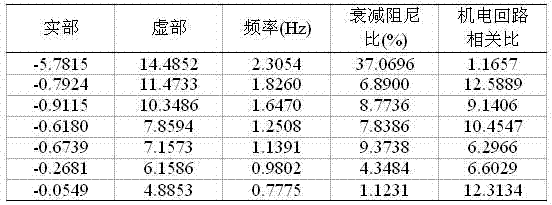
[0070] The Q-R eigenvalue analysis results of the 8-machine system are shown in Table 2. 0.77Hz is the mode with the weakest damping and...
PUM
 Abstract
Description
Claims
Application Information