
Stator vane for 3D composite blower

A guide vane, 3D technology, applied in the direction of supporting elements of blades, textiles and paper, liquid fuel engines, etc.

Active Publication Date: 2013-11-27
SN DETUDE & DE CONSTR DE MOTEURS DAVIATION S N E C M A
View PDF3 Cites 0 Cited by
  • Summary
  • Abstract
  • Description
  • Claims
  • Application Information

AI Technical Summary

Problems solved by technology

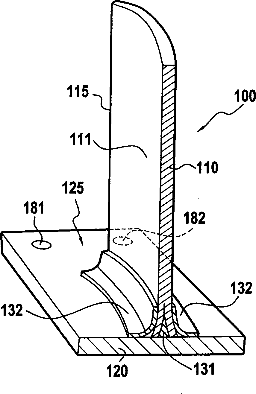
Therefore, the force transmission between the airfoil 110 and the platform 120 is difficult to ensure
Also, adding these parts requires a lot of additional manufacturing work, resulting in higher manufacturing costs

Method used


Image

  • Stator vane for 3D composite blower
  • Stator vane for 3D composite blower
  • Stator vane for 3D composite blower

Examples


Embodiment Construction

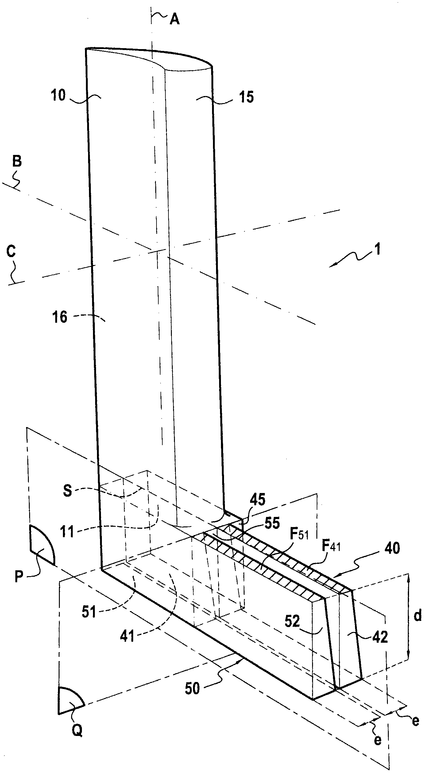
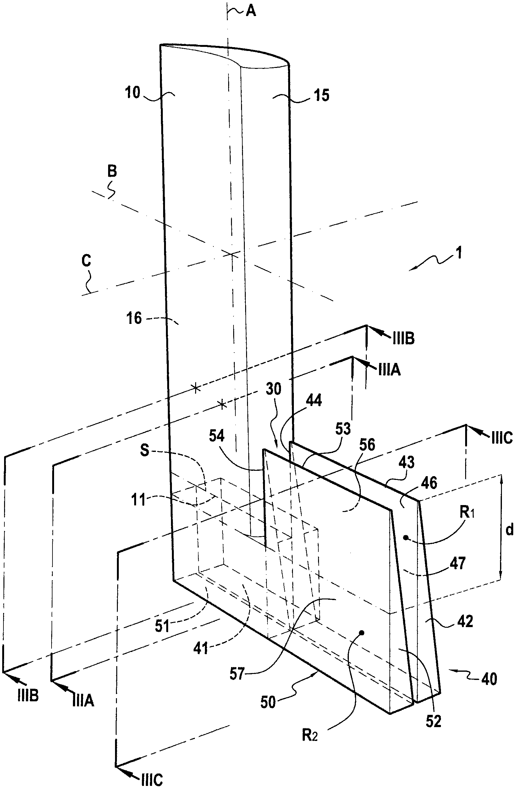
[0035] The steps of the method of manufacturing the guide vane of the present invention are schematically shown in Figure 1A , 1B , 1C, 1D and 1E. The preform 1 is a fiber structure made of fiber components. These fibrous members may be, for example, fibres, coarse fibers of hemp or interwoven microfibers. These fibers may be any reinforcing fibers such as carbon fibers, glass fibers, Kevlar fibers or combinations of these fibers. In the description below, this preform is made by 3D weaving of fibers. Alternatively, it can be made by 3D interweaving of fibers.

[0036] Such as Figure 1A As shown in , the preform 1 comprises a first portion 10 forming a guide vane airfoil. The main direction of this first portion 10 extends along the longitudinal axis A, about which the shape of the first portion 10 is slightly curved. The width of the first portion 10 extends along a transverse axis B perpendicular to the axis A, and the thickness of the first portion 10 extends along...


PUM


Abstract

A method of fabricating a guide vane. The method produces a fiber preform by 3D weaving a single piece, the preform including a first portion extending along the longitudinal axis and constituting the preform for an airfoil of the vane, and at a longitudinal end of the first portion, a second portion constituting the preform for the platform of the vane, the second portion being produced as a first layer and a second layer facing the first layer and separated from the first layer by unlinking without cutting while producing the preform; folding the first and second layers such that each of them lies in a plane perpendicular to the longitudinal axis, substantially symmetrically to each other relative to the first portion, and such that a first region of the first layer covers a second region of the second layer in front of a front edge of the first portion; conforming the preform in a mold; and densifying the preform with a polymer matrix.

Description

technical field [0001] The invention relates to a method of manufacturing guide vanes (outlet guide vanes / inlet guide vanes (OGV / IGV)). Background technique [0002] In structures where weight reduction is desired, such as turbines, guide vanes (e.g. fan guide vanes, low-pressure guide vanes) are made of a composite material with a polymer matrix made of, for example, carbon, glass or Kevlar of fiber reinforcement. The density of such composite materials is significantly lower than that of commonly used light alloys, and they offer better mechanical properties (in terms of rigidity and resistance to damage). [0003] More recent composites are made by fabricating 3D fiber preforms, such as weaving three-dimensional fibers. Such a preform is then densified with a polymer in which the yarns of the preform are embedded within a solid polymer matrix to produce a finished composite part. [0004] A known technique of pre-forming this densification is by means of liquids, for ...

Claims


Application Information

Patent Timeline
Patent Type & Authority Patents(China)
IPC IPC(8): B29C70/24F01D5/14F01D5/28B29B11/16D03D25/00F04D29/02F04D29/54B29C70/48B29C70/44
CPCB29B11/16F05D2230/20F05D2240/12D10B2505/02F04D29/542B29C70/48B29C70/24B29L2031/08F01D5/28D03D25/005B29C70/443F04D29/646F05D2300/6012F04D29/023F05D2300/603F05D2240/80Y10T29/49337Y10T29/49336Y10T29/49321
Inventor 奥利维耶·贝尔蒙特吉恩·诺埃尔·马修泽维尔·米利尔
Owner SN DETUDE & DE CONSTR DE MOTEURS DAVIATION S N E C M A
Learn More