
Device for analysing the surface of a substrate

A substrate and reference pattern technology, applied in the direction of using optical devices, measuring devices, analyzing materials, etc., can solve the problems of long measurement process time, time-consuming acquisition process, prolonging the time for smooth panels to stop, etc., to achieve low cost, reduce small size effect

Active Publication Date: 2011-08-31
SAINT-GOBAIN GLASS FRANCE
View PDF4 Cites 10 Cited by
  • Summary
  • Abstract
  • Description
  • Claims
  • Application Information

AI Technical Summary

Problems solved by technology

This sequence of acquisitions is therefore time consuming and also prolongs the time it takes for the smooth panel to stop
[0018] Therefore, the device described in said patent US 6 208 412 and its measurement process require an excessively long measurement process time, considering the very short time used in industrial production lines for making retention or rejecting a smooth panel. The measurement process takes too long

Method used


Image

  • Device for analysing the surface of a substrate
  • Device for analysing the surface of a substrate
  • Device for analysing the surface of a substrate

Examples


Embodiment Construction

[0053] The figures are not drawn to scale for easier study.

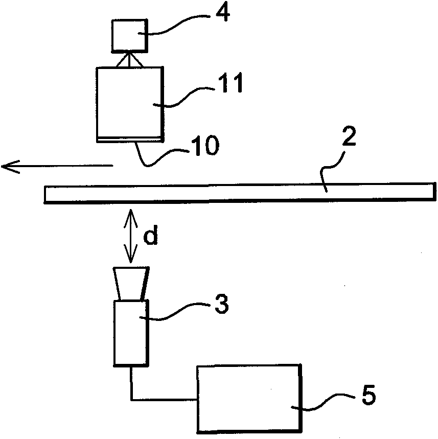
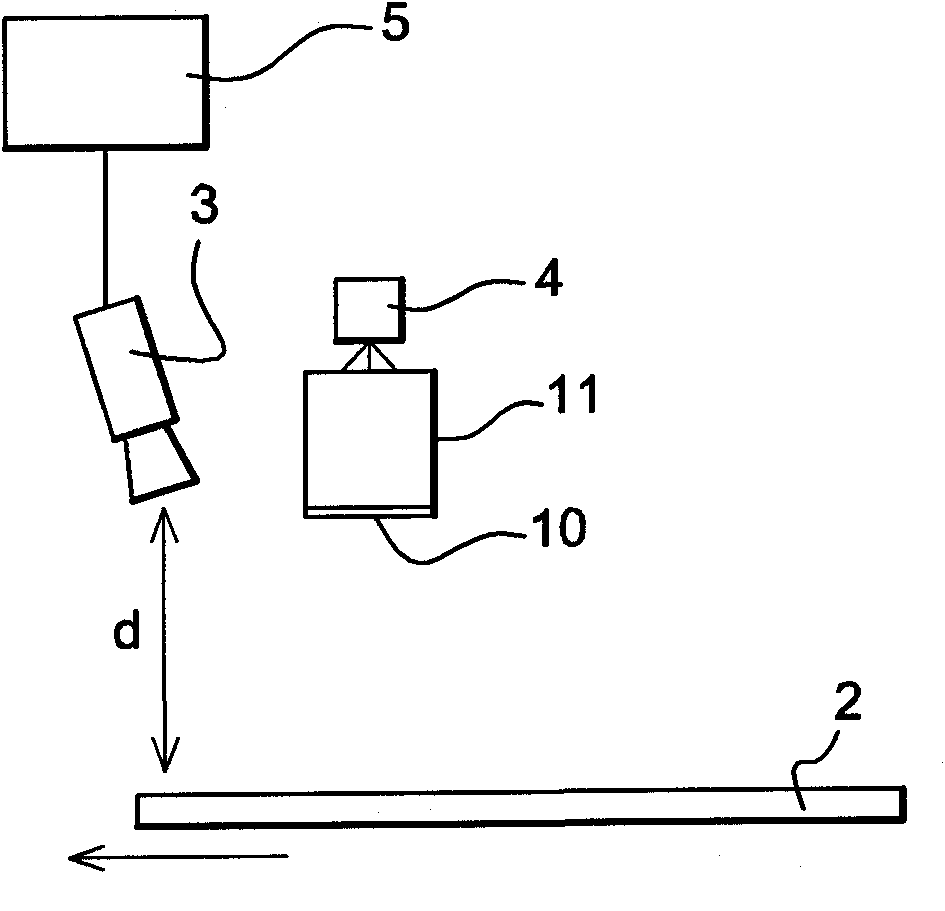
[0054] exist figure 1 with 2 The device 1 shown in allows the analysis of defects in a transparent substrate 2, eg a smooth panel, in transmission and in reflection, respectively. The device comprises a reference pattern 10 , image capture means 3 , eg a matrix camera, a reference pattern illumination system 4 and suitable processing / computing means 5 .

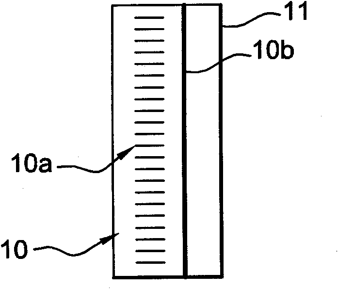
[0055] The reference pattern 10 is formed on one side of the support panel 11 facing the substrate to be measured. It will be described more fully later.

[0056] In transmission ( figure 1 ), the transparent substrate 2 is placed between the reference pattern 10 and the camera 3, and the objective lens of the camera points to the substrate.

[0057] In reflection ( figure 2 ), the substrate 2 with a mirror surface is placed in the front of the reference pattern 10 and the camera 3, the objective lens of the camera is in the same plane as that of the referen...


PUM


Abstract

The invention relates to an analysis device (1) for analysing the transparent or specular surface of a substrate (2), said device comprising a raster (10) located opposite the surface of the substrate to be measured, a video camera (3) for capturing at least one image of the raster deformed by the measured substrate, a raster lighting system (4), and an image-processing and digital analysis means (5) connected to the video camera (3). According to the invention, the video camera (3) is a matrix array camera, the raster (10) is provided on a substrate (11) having an oblong shape and is bidirectional in that it comprises a first pattern (10a) extending along a first direction and along the smallest extension of the substrate, the first pattern being transversely periodical to the smallest extension, and a second pattern (10b) extending in a second direction perpendicular to the first pattern and along the largest extension of the substrate.

Description

technical field [0001] The invention relates to a device for analyzing specular or transparent surfaces of a substrate, so that in particular optical defects on the surface of said substrate or within its volume can be detected. Background technique [0002] In general, it is desirable in industry to achieve greater and greater control over the quality of manufactured products. In particular, there is currently a need to invariably evaluate the level of optical quality of glossy panels. [0003] In particular, it may be desirable to select flat glass off the production line in order to use it for a particular application, such as reflective mirrors designed for scientific applications, laminated (laminated) smooth panels designed for the building industry, e.g. Smooth panels for cars specially designed for highly sloped windshields, or flat thin glass for display screens. [0004] In general, modern motor vehicle windscreens are specifically monitored for their optical qua...

Claims


Application Information

Patent Timeline
IPC IPC(8): G01N21/958G01B11/30G01B11/25
CPCG01N2021/9586G01N21/958G01N21/896G01B11/2513
Inventor M·皮雄F·达韦纳
Owner SAINT-GOBAIN GLASS FRANCE
Learn More