
Geological compass

A compass and geology technology, applied in the directions of compass, measuring device, mapping and navigation, can solve the problems of inclination measurement error, low work efficiency, inclination angle measurement error, etc., to improve accuracy and efficiency, improve work efficiency, reduce The effect of small error propagation

Inactive Publication Date: 2011-09-07
CHINA UNIV OF GEOSCIENCES (WUHAN)
View PDF5 Cites 23 Cited by
  • Summary
  • Abstract
  • Description
  • Claims
  • Application Information

AI Technical Summary

Problems solved by technology

When using the traditional geological compass to measure the inclination angle, it is necessary to use a sight to aim at the linear structure, but manual operation of the traditional geological compass cannot ensure that the bottom surface of the compass is in the vertical plane where the linear structure is located, and the bottom surface of the compass deviates from the vertical plane where the linear structure is located When , there will be a measurement error of the inclination angle, so generally only schematic measurements can be made
[0004] (2) The operation is cumbersome when measuring the shape of the planar structure, and the inclination angle is prone to measurement errors
After the inclination is measured, to measure the inclination, one of the long sides of the geological compass needs to be close to the layer and then rotate the compass. During the flipping process, the geological compass is prone to deviation, which will cause inclination measurement errors
[0005] (3) The inclination direction and inclination angle of the linear structure, and the inclination and inclination angle of the planar structure need to be measured twice, and the circular level and the tube level need to be adjusted to the level. The operation is cumbersome and the work efficiency is low, and The error of manually adjusting the level is large

Method used


Image

  • Geological compass
  • Geological compass
  • Geological compass

Examples


Embodiment Construction

[0029] A specific embodiment of the present invention will be further described in detail below in conjunction with the accompanying drawings.

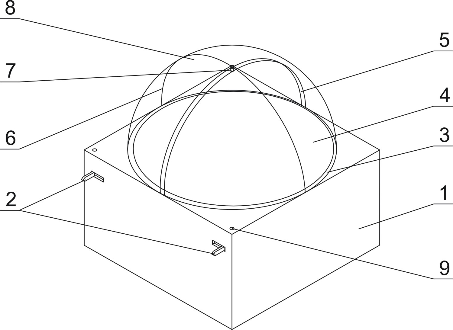
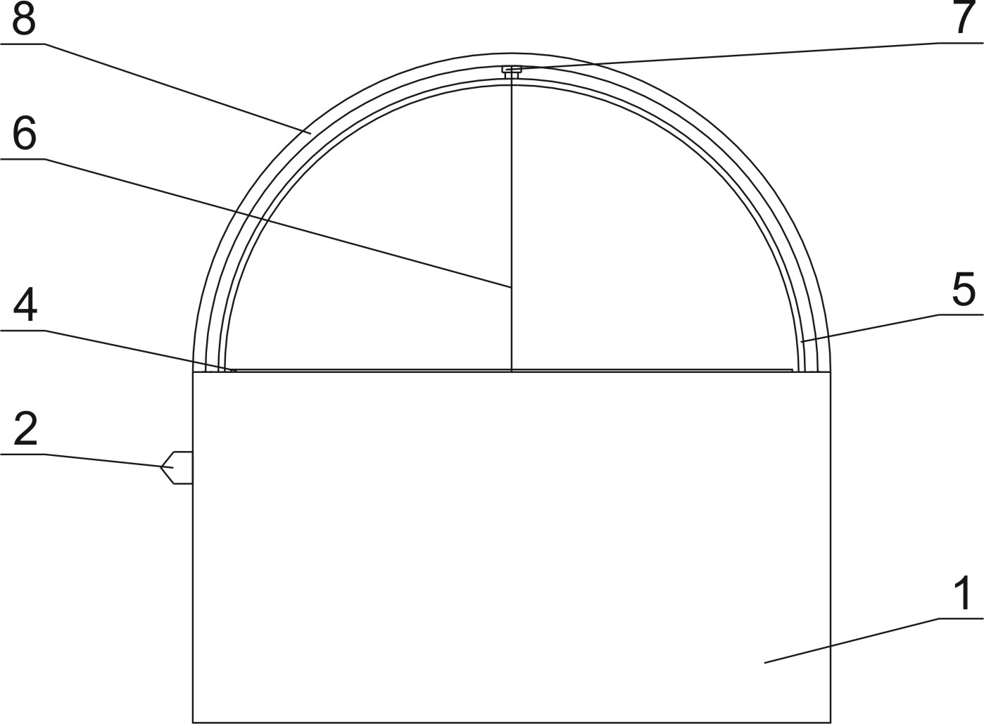
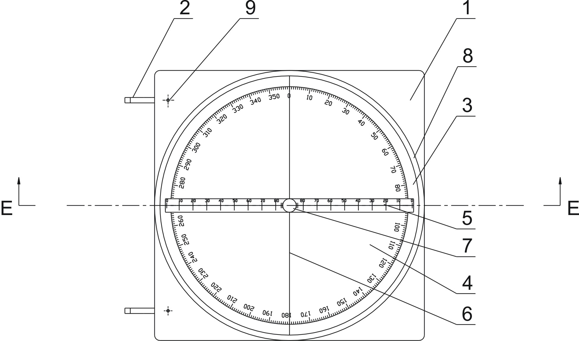
[0030] As shown in the figure, a geological compass of the present invention includes a base 1 , a sight 2 , a float 3 , an azimuth dial 4 , a goniometer 5 , and a transparent cover 8 .

[0031] Wherein: the base 1 is made of shock-absorbing, anti-leakage, wear-resistant, non-deformable, lightweight, weakly magnetic or non-magnetic materials, such as hard PVC, PSU, etc. The bottom surface of the base 1 is a square, and the side is a rectangular parallelepiped. The top surface of the base 1 has a hemispherical groove whose diameter is the size of the inner diameter of the transparent cover 8 .

[0032] The sight 2 is a pair of protrusions symmetrically arranged in two notches on the side of the base 1, and can be made of wear-resistant, non-deformable, high-strength materials, such as plexiglass. The front end of the projection is a t...


PUM


Abstract

The invention discloses a geological compass which comprises a base, a sighting device, an azimuth circle, an angle meter and a semi-spherical transparent cover, wherein the sighting device is arranged at the side surface of the base and provided with two sharp ends positioned in the same horizontal line; the top surface of the base is provided with a semi-spherical groove, the diameter of the groove is same as the inner diameter of the transparent cover, and the groove is internally provided with floating liquid; the azimuth circle is a disk with magnetic poles and floated on the floating liquid; the transparent cover is arranged above the groove and connected with the top surface of the base in a sealing manner; an alignment line is arranged on the transparent cover and is half of a large circle passing through the top end of the transparent cover, and the plane where the alignment line is in is parallel with a straight line where the two sharp ends are in; the angle meter is a circle marked with scales and is arranged in a space enclosed by the transparent cover and the groove, rotating shafts are arranged at the top end of the transparent cover and the bottom end of the groove, and the upper end and the lower end of the angle meter are respectively hinged with the rotating shafts; and the straight line where the rotating shaft is separates the angle meter into two semicircular rings, and one semicircular ring is heavier than the other semicircular ring. The geological compass has the advantages of simple construction, convenience for operation and accuracy in measurement.

Description

technical field [0001] The invention belongs to the field of geological survey, and in particular relates to a geological compass used for measuring position, orientation, occurrence, slope and aspect in geological survey. Background technique [0002] The geological compass is of great significance in geological work and is known as one of the three treasures of geologists. There are many styles of geological compass, but their structure is basically the same. Commonly used is the circular basin type geological compass, which is composed of a magnetic needle, a dial, an inclinometer, an aiming target plate, a level, etc., and is installed in a copper, aluminum or wooden circular basin. Geologists face various geological entities, although their structure types, origins, scales and shapes vary widely, but from a geometric point of view, their basic structures can be summarized as linear structures and planar structures. Correspondingly, the measurement of various geologica...

Claims


Application Information

Patent Timeline
IPC IPC(8): G01C17/08G01C1/00
Inventor 黄磊唐辉明葛云峰张延志
Owner CHINA UNIV OF GEOSCIENCES (WUHAN)
Learn More