Organic tandem solar cells

A technology of organic and organic photovoltaic devices, applied in the field of organic tandem solar cells, can solve the problems of low device efficiency and energy loss, etc.

Inactive Publication Date: 2011-09-07
RGT UNIV OF MICHIGAN
View PDF5 Cites 14 Cited by
  • Summary
  • Abstract
  • Description
  • Claims
  • Application Information

AI Technical Summary

Problems solved by technology

Energy is lost in the process, which results in lower device efficiency

Method used


Image

  • Organic tandem solar cells
  • Organic tandem solar cells
  • Organic tandem solar cells

Examples


Embodiment

[0160] Exemplary device

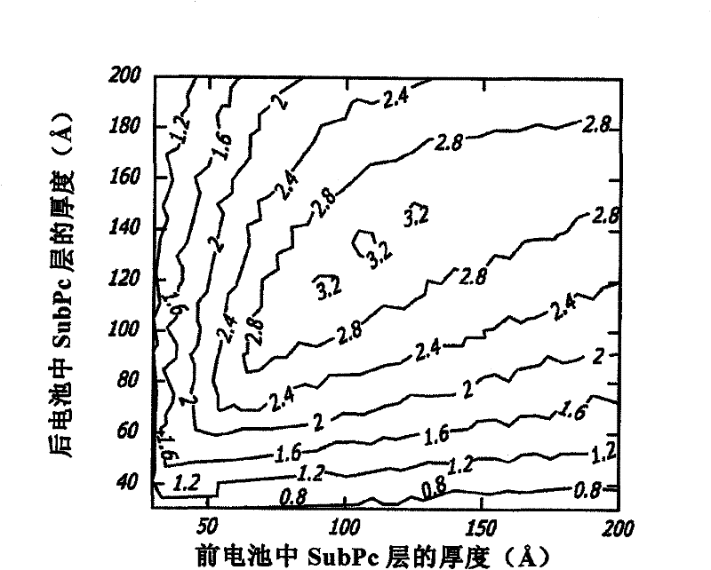
[0161] further reference Figure 10 , for the bottom cell (which is close to the ITO anode side), SubPc / C 60 Nanocrystalline cell with 120 deposited as a continuous wetting layer SubPc, then set the thickness to 1500 Nanocrystalline C 60 / SubPc multilayer deposited on top of the original SubPc wetting layer. Next, apply 700 layer of C60 to complete the front cell. For the middle layer, Ag is used as a recombination center to balance the photocurrent generated in the front and back cells.

[0162] The top cell (which is close to the Ag cathode side) is a CuPc / C60 nanocrystalline cell with 50 CuPc acts as a continuous wetting layer. On top of the pristine CuPc wetting layer is a thickness of 468 Nanocrystalline C 60 / CuPc multilayer, then 158 C60 donor layer and 80 BCP barrier. Metal Ag was used as the cathode.

[0163] other devices

[0164] Initial stacked device assemblies were fabricated by vacuum thermal evaporation. In l...


PUM


Abstract

There is disclosed an organic photovoltaic device comprising two or more organic photoactive regions located between a first electrode and a second electrode, wherein each of the organic photoactive regions comprise a donor, and an acceptor, and wherein the organic photovoltaic device comprises at least one exciton blocking layer, and at least one charge recombination layer, or charge transfer layer between the two or more photoactive regions. It has been discovered that a high open circuit voltage can been obtained for organic tandem solar cells according to this disclosure. Methods of making and methods of using are also disclosed.

Description

[0001] Cross References to Related Applications [0002] This application is based on U.S. Provisional Patent Application No. 61 / 100,583, filed September 26, 2008, entitled "Organic Tandem Solar Cells" and filed November 28, 2008, entitled "Comprising CuPc and U.S. Provisional Patent Application No. 61 / 118,529 for "Tandem Organic Solar Cells Incorporating CuPc and SubPc as Donor Materials" (Tandem Organic Solar Cells Incorporating CuPc and SubPc as Donor Materials), the entire contents of both provisional patent applications are hereby Cited for reference. [0003] joint research agreement [0004] The claimed invention was made by, on behalf of, and / or jointly with, parties to, and / or under a joint university-corporate research agreement: The Regents of the University of Michigan and Global Photonic Energy Corporation ). The agreement was in effect on and before the time this claimed invention was made, and this claimed invention was made as a result of activities underta...

Claims


Application Information

Patent Timeline
Patent Type & Authority Applications(China)
IPC IPC(8): H01L51/42H01L27/30
CPCH01L51/0053B82Y10/00H01L51/0078H01L27/302H01L51/4246H01L51/4253H01L51/0046H01L2251/308Y02E10/50Y02E10/549Y02P70/50H10K30/57H10K85/211H10K85/621H10K85/311H10K30/211H10K30/30H10K2102/103H10K30/00
Inventor 史蒂芬·R·福里斯特布赖恩·E·拉希特韦国丹
Owner RGT UNIV OF MICHIGAN
Why Eureka
Try Eureka