Micro-pressure cooker

A technology for pots and pot lids, which is applied to household utensils, kitchen utensils, lids of cooking utensils, etc., can solve the problems of delaying the cooking time, not considering the negative pressure of opening the lid and the positive pressure of closing the lid, etc., so as to reduce the consumption of energy. , the effect of precise temperature control

Active Publication Date: 2011-09-14
DEA GENERAL AVIATION HLDG CO LTD
View PDF8 Cites 35 Cited by
  • Summary
  • Abstract
  • Description
  • Claims
  • Application Information

AI Technical Summary

Problems solved by technology

Secondly, the cooker of this kind of structure, because its inner pot works in a sealed state, there will be a problem of cold air overflowing before the water boils, so the accumulation of cold air in the pot can also cause the pot cover to turn frequently, and then the heater It starts or stops frequently before the water reaches the boiling point, which greatly delays the cooking time; and the cooker with this structure does not consider the negative pressure of opening the cover and the positive pressure of closing the cover when it is not working.

Method used


Image

  • Micro-pressure cooker
  • Micro-pressure cooker
  • Micro-pressure cooker

Examples


Embodiment 1

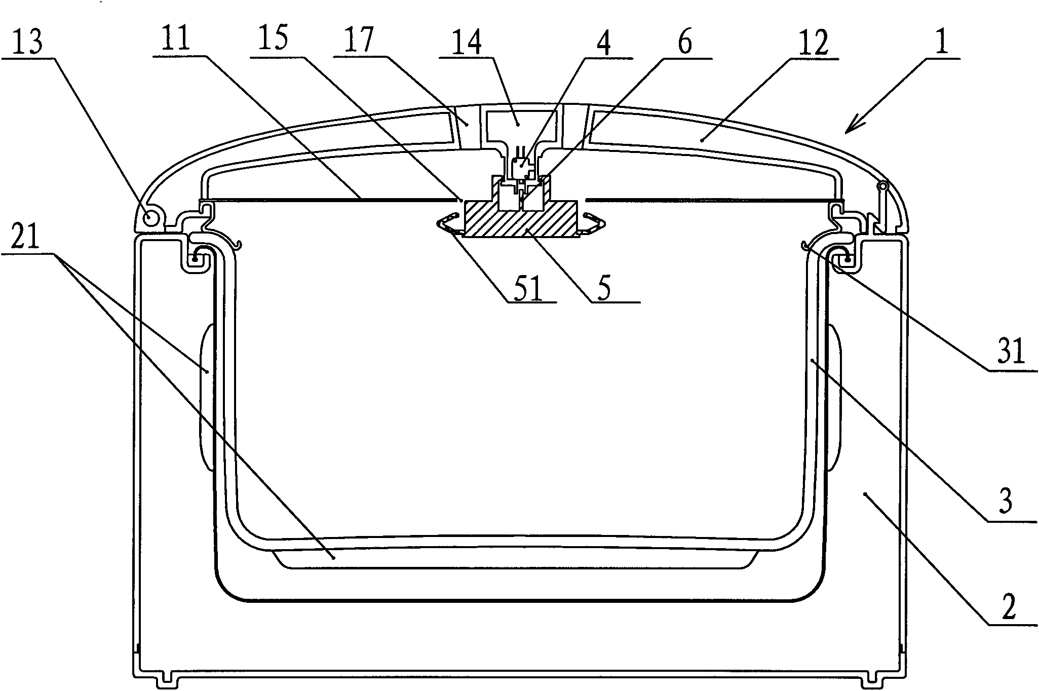
[0038] Such as figure 1 As shown, a micro-pressure cooker includes a pot cover 1, a pot body 2, an inner pot 3 and a heater 21, wherein the pot body 2 is the main bearing part of the micro-pressure cooker, and an inner pot is arranged inside 2. The heater 21 and the electric control system of the micro-pressure cooker, the pot cover 1 is located on the top of the pot body 2 and is provided with an inner pot sealing ring 31 between the inner pot 2, The pot cover 1 is provided with a signal switch 4 .

[0039] The pot cover 1 includes an outer shell 12 and an inner cover 11 , and the pot cover 1 is hingedly connected by a hinge device 13 provided between the outer shell 12 and the pot body 2 so that it can be flipped. The inner pot 3 is arranged in the pot body 2, and the outer periphery (side or / and bottom) of the inner pot 3 is provided with a heater 21, and the heater 21 can be attached to the inner pot 3. The outer surface can also be pasted on the outer surface of the out...

Embodiment 2

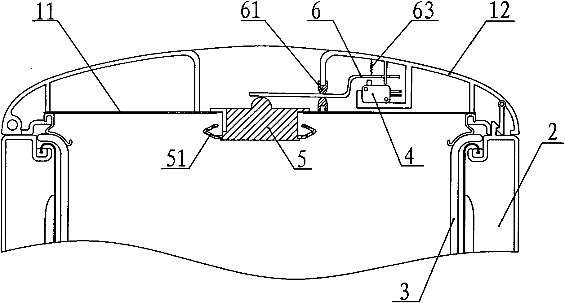
[0046] Such as image 3 As shown, the difference from Embodiment 1 is that the first air release valve core 5 is T-shaped and hangs in the first cover hole 15, and the signal switch 4 is not located on the first air release valve core 5. But the above is offset by a certain distance, the transmission arm 6 is arranged laterally and a fulcrum 61 is set at the middle position of the transmission arm 6, and a sealing device is set between the fulcrum 61 and the transmission arm 6, so that the pot can The exhausted steam will not enter the area where the signal switch 4 is located, which protects the safety of the signal switch 4 in use. Next, return spring 63 is set on the right side of described fulcrum 61, and one end of described return spring 63 is fixedly connected on the described pot cover 1, and the other end is connected with described transmission arm 6, thereby described return spring 63 can not only increase The rotational force of transmission arm 6, and described t...

Embodiment 3

[0048] Such as Figure 4 As shown, the difference from the second embodiment is that the signal switch 4 is arranged on the upper part of the pot body 2, and a water-proof cover 7 is arranged between the signal switch 4 and the transmission arm 6; Figure 5 As shown, the water avoiding cover 7 is in the shape of a mountain, wherein the two side arms 72 of the water avoiding cover 7 are provided with barbs 73 and are snapped on the outer wall of the pot body 2 in a movable up and down manner. The middle arm body 71 of water avoiding cover 7 pushes on the button of described signal switch 4; The upright wall 22 adapted to the annular wall 73 , the upright wall 22 is inserted into the annular wall 73 . In this way, the water-proof cover 7 can slide on the vertical wall 22 but will not come out, and external pollutants will not enter the pot body 2; secondly, the signal line of the signal switch 4 can not be connected. onto the lid 1. In addition, a reset spring (not shown) can...


PUM


Abstract

The invention discloses a micro-pressure cooker, which comprises a pot body, an inner pot, a pot cover and a heater, wherein an inner pot seal ring is arranged between the pot cover and the inner pot; the pot body or the pot cover is provided with a signal switch; the pot cover is provided with a first cover hole which is communicated with an accommodating cavity of the inner pot; a first air release valve core which can move up and down is arranged in the first cover hole; a gap is reserved between the first air release valve core and the pot cover; the lower part of the first air release valve core is provided with a first seal ring; a gap is reserved between the first seal ring and the pot cover; a transmission arm is arranged between the signal switch and the first air release valve core; and when the first air release valve core moves upwards, the first seal ring blocks the first cover hole, and the first air release valve core drives the signal switch to act through the transmission arm. Through the micro-pressure cooker, energy consumption is greatly reduced, temperature is accurately controlled, and the pot cover is smoothly opened and closed. Due to the characteristics, the micro-pressure cooker can be applied to kitchenware such as an electric cooker, a soup cooker, a slow cooker and the like.

Description

technical field [0001] The invention relates to an electric heating pot, in particular to an electric heating pot working under a micro-pressure working state. Background technique [0002] The lid of the traditional electric rice cooker is provided with vent holes leading directly to the outside air. There is basically no pressure in the pot, and the boiling water in the pot will take away a large amount of heat, which makes the energy consumption of this traditional electric rice cooker very high. High; Secondly, in order to maintain the heat required for boiling the water in the pot, the power and volume of the heater must be appropriately enlarged. Pressure cookers, especially electric pressure cookers that have been developed in recent years, although the energy consumption has been greatly reduced, the high pressure in the pot not only damages the food in the pot, but also requires a high structural strength of the pot body, otherwise it is very easy to explode, so the...

Claims


Application Information

Patent Timeline
Patent Type & Authority Applications(China)
IPC IPC(8): A47J27/00A47J36/06A47J36/38
Inventor 简伟文邹邦明李孜宇韦兴龙
Owner DEA GENERAL AVIATION HLDG CO LTD
Why Eureka
Try Eureka