Full automatic pipe cutting machine

A pipe cutting machine, fully automatic technology, applied in the direction of pipe shearing device, shearing device, shearing machine accessory device, etc., can solve the problem of unsatisfactory high-precision products, affecting the straightness of pipe cutting, and high labor intensity of operators and other problems, to achieve the effect of high degree of automation, high cutting efficiency and simple structure

Inactive Publication Date: 2011-09-14
中臻工业有限公司
View PDF6 Cites 60 Cited by
  • Summary
  • Abstract
  • Description
  • Claims
  • Application Information

AI Technical Summary

Problems solved by technology

The straightness of the operator's hand push directly affects the straightness of the pipe cutting incision. The straightness of the pipe cutting in this way is low and cannot meet the requirements

Method used


Image

  • Full automatic pipe cutting machine
  • Full automatic pipe cutting machine
  • Full automatic pipe cutting machine

Examples


Embodiment 1

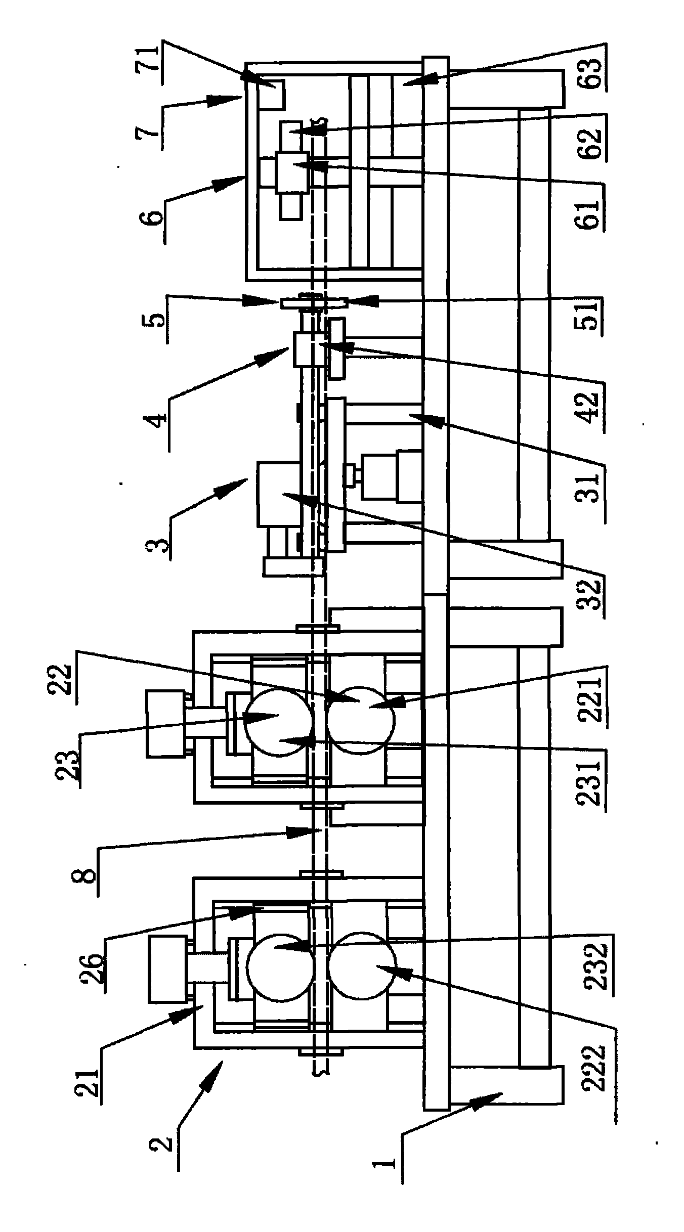
[0026] Such as figure 1 , figure 2 As shown, the present invention is a fully automatic pipe cutting machine, which includes a feeding drive part 2, a cutting drive part 3, a pipe fitting clamping part 4, a cutting part 5, and a discharge part, which are sequentially arranged on a workbench 1. 6 and the cutting and measuring part 7; the feeding driving part 2 includes a driving bracket 21, and the driving bracket 21 is provided with a vertically distributed driving wheel 22 and a rolling wheel 23, and the driving wheel 22 is connected to the step by a driving shaft 24. The feeder motor 25 is connected, and the rolling roller 23 is connected with the up and down adjustment mechanism 26 arranged on the driving bracket 21; the cutting driving part 3 includes a Slide rail 31, the cutting driving mechanism 32 of pipe fitting 8 is provided on the described workbench 1 of the side of described slide rail 31; Described pipe fitting clamping part 4 comprises the driving part 42 of pi...

Embodiment 2

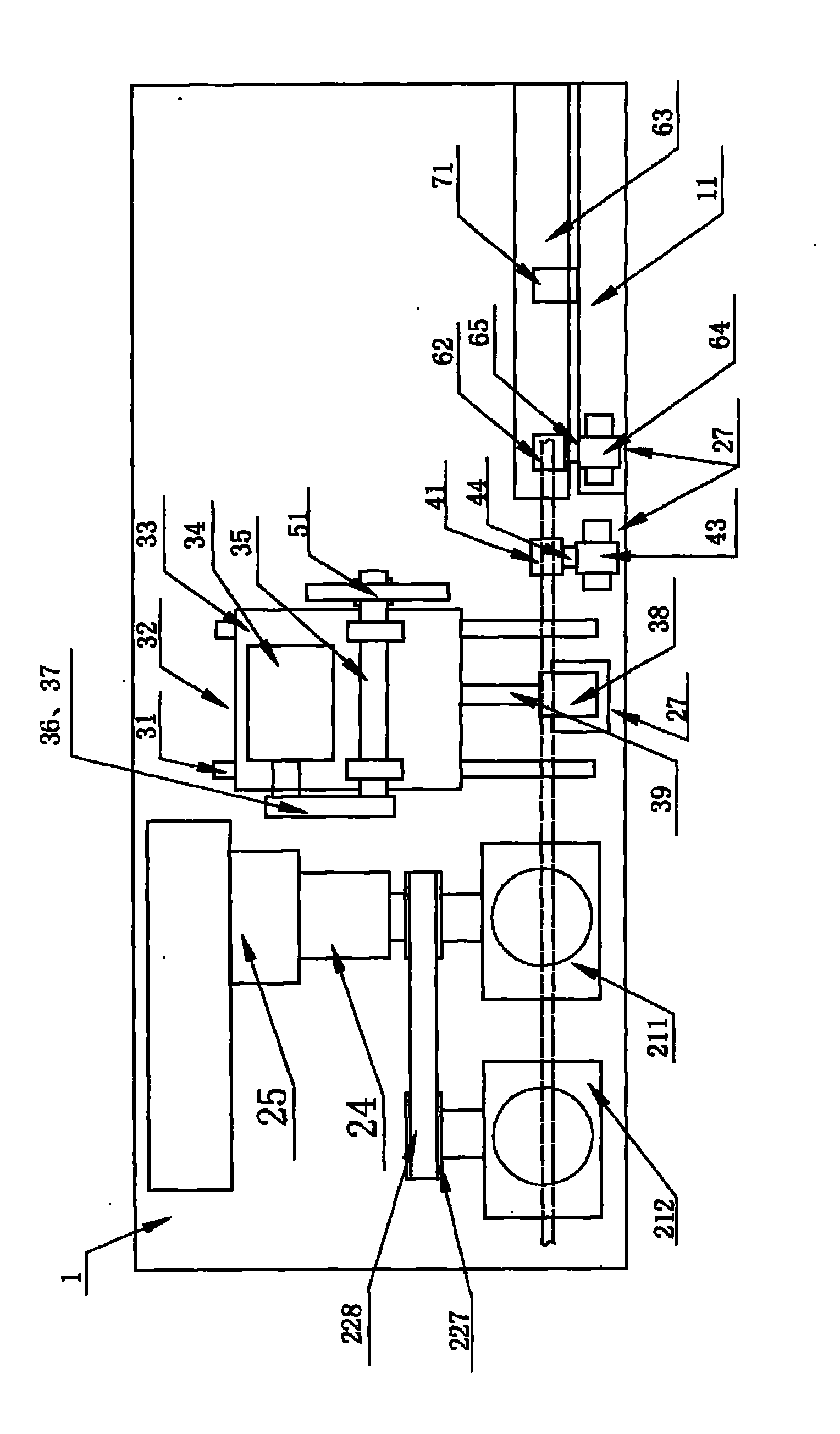
[0028] As shown in the picture, image 3As shown, on the basis of Example 1, in order to enable the cut pipe to be fed straight forward, and at the same time in order to increase the driving friction of the feed and distribute the friction evenly on the conveyed pipe, the The driving bracket 21 includes a main driving bracket 211 and an auxiliary driving bracket 212 arranged in a straight line, and a main driving wheel 221 and an auxiliary driving wheel 222 are respectively arranged on the main driving bracket 211 and the auxiliary driving bracket 212. The driving wheel 221 and the auxiliary driving wheel 222 are respectively supported on the main driving bracket 221 and the auxiliary driving bracket 222 through the main driving shaft 223 and the auxiliary driving shaft 224. A bearing 225 and a bearing bracket 226 are arranged between the main driving bracket 211 and the auxiliary driving bracket 212, and the bearing bracket 226 is closely matched with the main driving bracket...

Embodiment 3

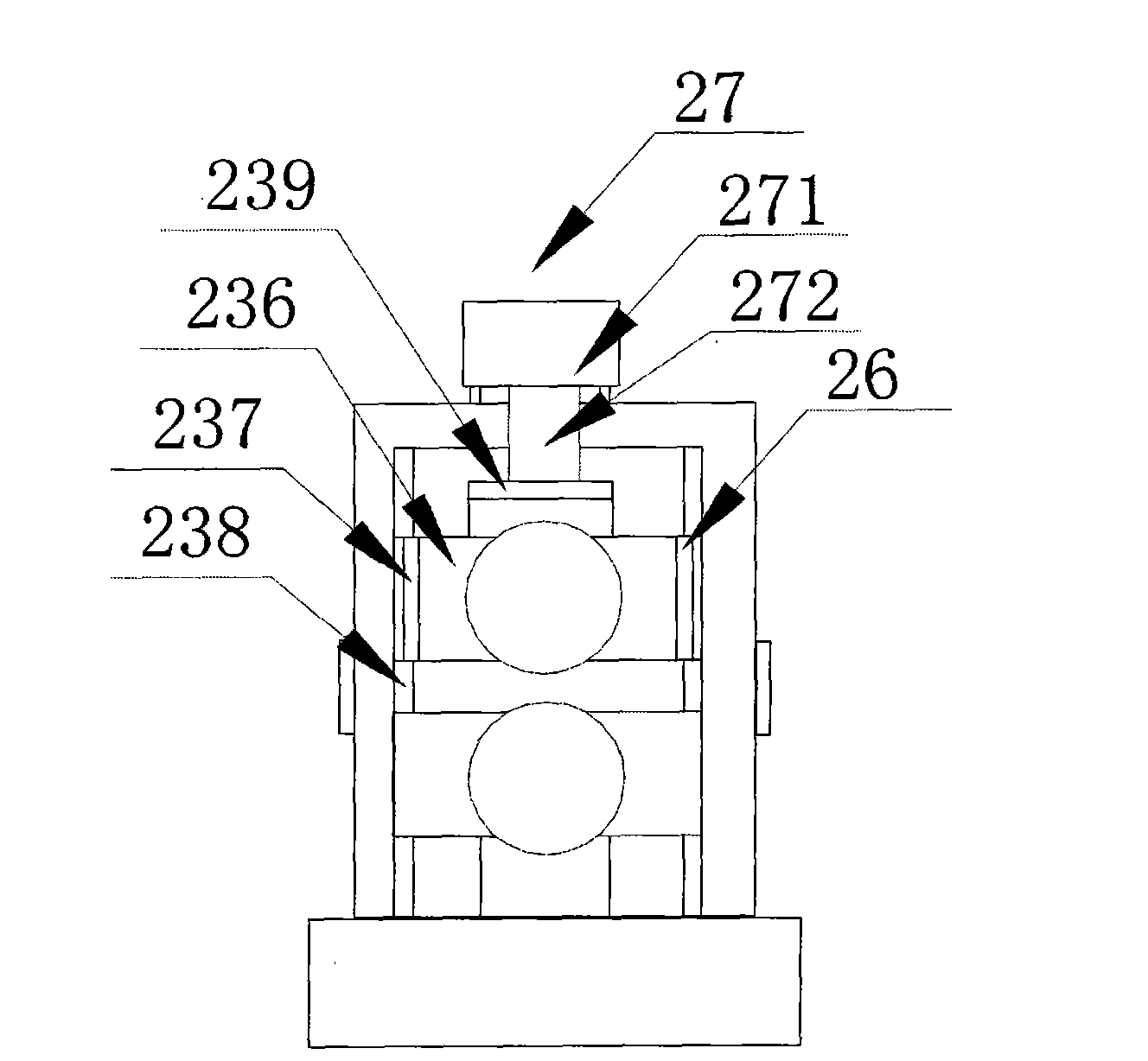
[0030] Such as figure 1 , Figure 4 As shown, on the basis of Embodiment 2, in order to make the driving bracket suitable for cutting pipes of different specifications, and at the same time to easily adjust the friction force in the pipe fittings transmission process, on the main driving bracket 211 and the auxiliary driving bracket 212 Main rolling wheel 231 and auxiliary rolling wheel 232 are also provided respectively. The bearings 235 and the bearing brackets 236 on both sides of the auxiliary rolling shaft 234 are connected with the vertical adjustment mechanism 26 on the main driving bracket 211 and the auxiliary driving bracket 212 .


PUM


Abstract

The invention discloses a full automatic pipe cutting machine. The pipe cutting machine comprises a feeding drive part, a cutting drive part, a pipe clamping part, a cutting part, an unloading part and a cutting measurement part which are sequentially arranged on an operating platform, wherein the feeding drive part conveys pipes to the cutting part by a driving wheel and a rolling wheel, then the pipes are cut off by a cutting tool driven by the cutting drive part; the driving wheel of the pipe cutting machine is driven by a stepping motor, and the lengths of the cut pipes can be accurately detected and controlled according to the electrical signals of stepping quantity of the stepping motor and the data of radius of the driving wheel; and in addition, the operating platform is also provided with an infrared distance measurement sensor, and the length accuracy of the cut pipe is jointly ensured by the electrical distance measurement signals and the movement detection signals of the stepping motor. By adopting the clamping feeding structure, the automatic cutting structure, the automatic clamping structure, the automatic unloading structure and the automatic cut pipe-length measurement and control mechanism, the degree of automation of the pipe cutting machine is improved.

Description

technical field [0001] The invention relates to pipe material cutting equipment, in particular to a fully automatic pipe cutting machine. Background technique [0002] At present, conventional pipe cutting machines generally use the following methods to cut pipes: [0003] 1. Manual feeding, using a ruler to determine the cutting length of the pipe fittings. Due to manual feeding, the operator visually inspects the length with his eyes. Due to the different viewing angles, the error of determining the length is at least ±0.8mm, which cannot meet the requirements of producing high-precision products. [0004] 2. Fix the assembly of the grinding wheel cutting machine, and the operator pushes the hose by hand to cut it off. The straightness of the operator's hand push directly affects the straightness of the incision of the pipe cutting. The straightness of the pipe cutting in this way is relatively low, which cannot meet the requirements of high-precision products. [0005]...

Claims


Application Information

Patent Timeline
IPC IPC(8): B23D21/00B23D33/02
Inventor 李东升申素琴包雅星
Owner 中臻工业有限公司
Why Eureka
Try Eureka