
Air-floating working platform for ultrasonic processing

A workbench and ultrasonic technology, applied in metal processing equipment, metal processing mechanical parts, manufacturing tools, etc., can solve the problems of high cost of hydraulic system, complex numerical control system, unfavorable wide application, etc., and achieve low cost, simple maintenance, and structure. simple effect

Inactive Publication Date: 2011-09-14
TIANJIN UNIV
View PDF5 Cites 11 Cited by
  • Summary
  • Abstract
  • Description
  • Claims
  • Application Information

AI Technical Summary

Problems solved by technology

The traditional methods of controlling the force in ultrasonic machining include hydraulic pressure, counterweight, etc., but the cost of the hydraulic system is high, and it is difficult to maintain itself. The method of using the counterweight needs to be used on a special machine tool, which is not conducive to its application in ultrasonic machining. widely used
At present, DMG adopts an adaptive method, which adjusts the feeding speed of the feeding system by monitoring the change of force during processing to achieve precise force control. Although this method has high precision in controlling force in ultrasonic processing, it requires Complex CNC system, high cost, and needs to be used on special machine tools

Method used


Image

  • Air-floating working platform for ultrasonic processing
  • Air-floating working platform for ultrasonic processing
  • Air-floating working platform for ultrasonic processing

Examples


Embodiment Construction

[0008] Below in conjunction with specific embodiment, and with reference to accompanying drawing, the present invention will be further described:

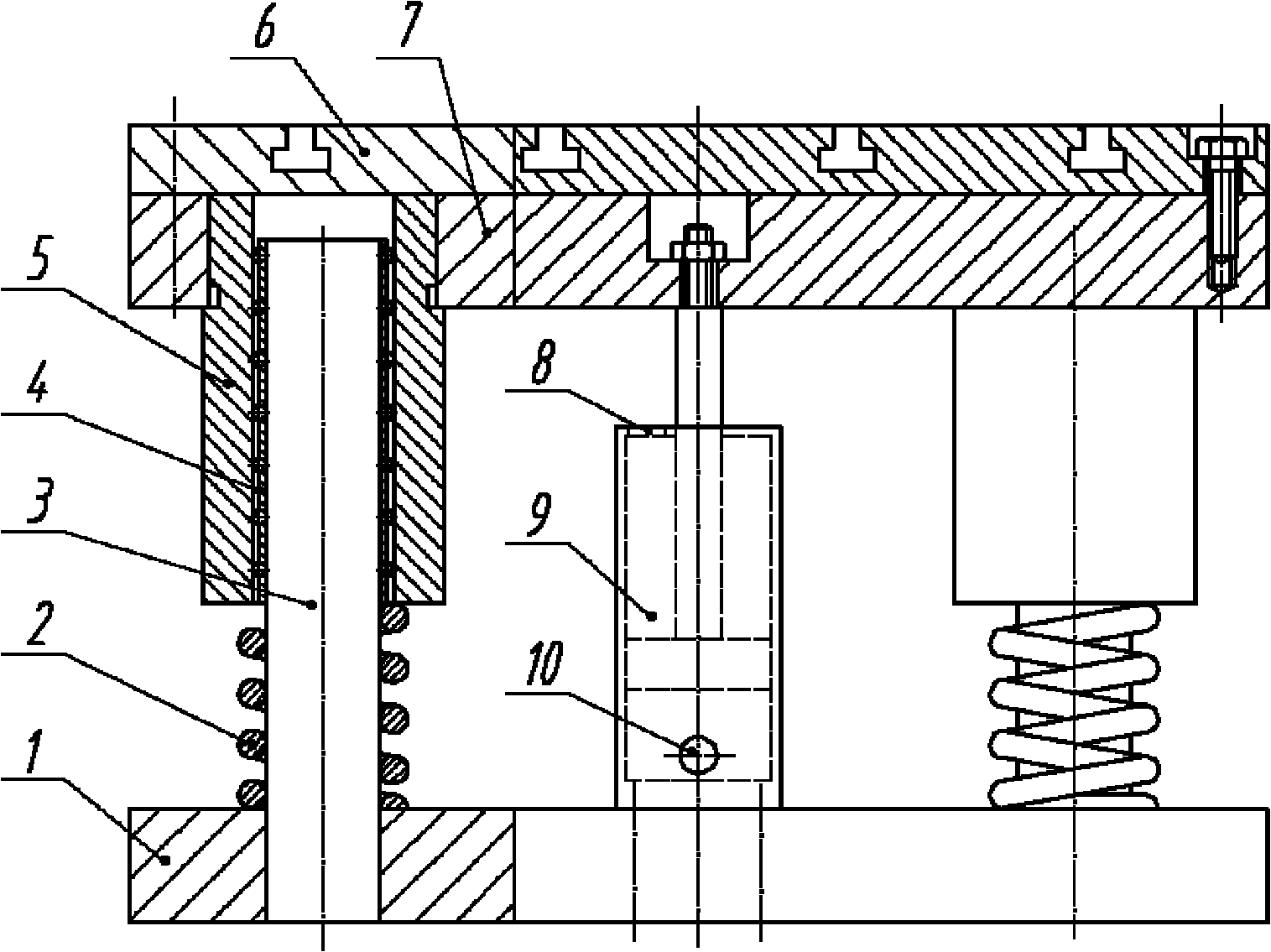
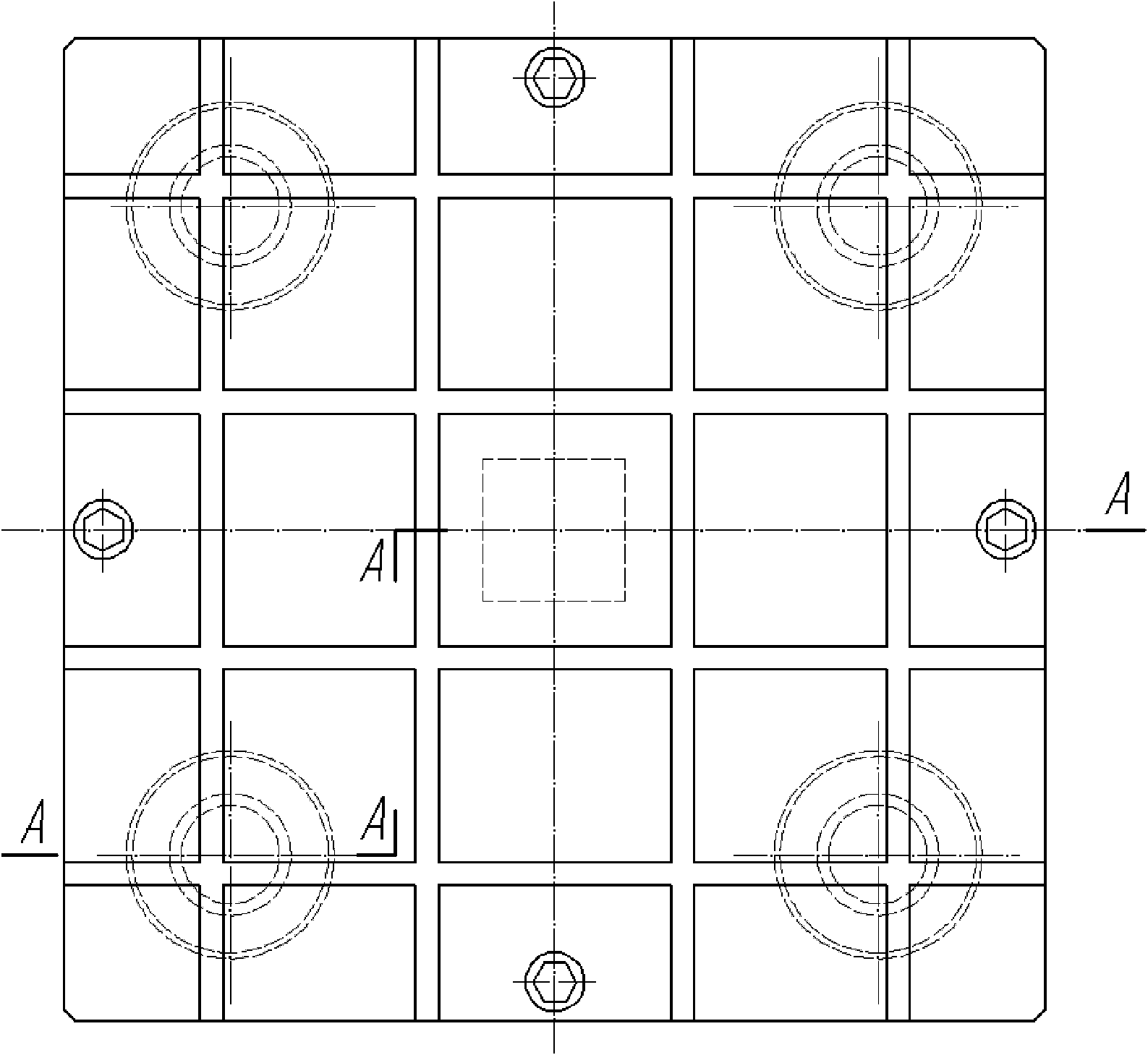
[0009] As shown in the accompanying drawings, an air-floating workbench for ultrasonic processing includes a base 1, at least four guide rails 3 are perpendicular to the base 1 and evenly and symmetrically distributed on the base 1, and one end of each guide rail 3 It is fixedly connected with the base 1 and its other end is placed in a guide sleeve 5 through the ball bushing 4, and a spring 2 is sleeved on the guide rail 3 between the bottom end of each guide sleeve 5 and the base 1, and each guide sleeve 5 The upper end of the upper end is fixedly connected with the support plate 7, and the work surface 6 is fixedly connected with the support plate 7. A cylinder 9 is arranged at the center of the base 1. The cylinder 9 and the piston rod of the cylinder 9 are arranged perpendicular to the base 1. The cylinder 9 has no piston. On...


PUM


Abstract

The invention discloses an air-floating working platform for ultrasonic processing, comprising a base; at least four guide rails are vertical to the base and are uniformly and symmetrically distributed on the base; one end of each guide rail is fixedly connected with the base and the other end of each guide rail is sheathed in a guide sleeve by a ball shaft; a spring is sheathed on the guide rail between the bottom end of each guide sleeve and the base; the upper end of each guide sleeve is fixedly connected with a supporting plate; the surface of the working platform is fixedly connected on the supporting plate; the central position of the base is provided with a cylinder; and a piston rod of the cylinder is vertically and fixedly connected with the supporting plate. The air-floating working platform can be conveniently installed on any common machine tool as an accessory part of the machine tool so as to realize constant-force control for the force in ultrasonic processing, so that a cutter, a workpiece and an ultrasonic vibration system are protected. The air-floating working platform has the advantages that the structure is simple, the volume is small, the complex electric control system is omitted, the use is convenient, the maintenance is simple, the cost is low and the air-floating working platform is applicable to large-scale production.

Description

technical field [0001] The invention relates to a machine tool accessory for ultrasonic processing, in particular to an air floating workbench for ultrasonic processing. Background technique [0002] Ultrasonic machining is widely used in the processing of hard and brittle materials, with high processing efficiency and good surface quality of workpieces. However, when the machine tool spindle is fed too fast and the force of ultrasonic machining workpiece is too large, it will damage the workpiece, resulting in cracks, broken, Fracture, etc., or the tool will be severely worn, and even destroy the ultrasonic vibration system in severe cases. In order to make good use of ultrasonic processing and protect the tool, workpiece and ultrasonic vibration system, it is necessary to control the force during ultrasonic processing to prevent it from being too large. The traditional methods of controlling the force in ultrasonic machining include hydraulic pressure, counterweight, etc....

Claims


Application Information

Patent Timeline
IPC IPC(8): B23Q1/25
Inventor 林彬刘礼平周凌云朱学明
Owner TIANJIN UNIV
Learn More