
Cutting tool for high-speed cutting

A cutting tool, high-speed cutting technology, applied in the field of metal cutting, can solve the problem of short effective contact length between fasteners and threaded holes, small effective contact area between fasteners and tool holders, large axial force and rotary centrifugal force, etc. problem, to achieve the effect of low production cost, simple and compact structure, and easy processing

Active Publication Date: 2011-09-14
ZHUZHOU CEMENTED CARBIDE CUTTING TOOLS CO LTD
View PDF4 Cites 1 Cited by
  • Summary
  • Abstract
  • Description
  • Claims
  • Application Information

AI Technical Summary

Problems solved by technology

In order to reduce the rotation load of the spindle of the machine tool, aluminum alloys with low density are generally used as tool materials, but the bending strength of aluminum alloys is only 1 / 4 to 1 / 2 of that of ordinary cutting tool materials. The cutting edge and the surrounding clamping parts will generate a large centrifugal force. Using the internal thread inlaid on the cutter body to clamp the toolholder will generate a large axial force and rotational centrifugal force. Due to stress fatigue, the thread is more likely to be damaged
This type of high-speed cutting tool is generally composed of a cutter body, a cutter holder, a wedge and a fastener. There is at least one set of grooves on the cutter body, the cutter holder and the wedge are placed in the groove, and the wedge is provided with a thread The fastener is installed in the threaded hole and the tool holder is pressed tightly. Since the thickness of the wedge is generally thin, the effective contact length between the fastener and the threaded hole is short, and the fastener may occur during high-speed cutting. At the same time, due to the small effective contact area between the fastener and the toolholder, long-term use is more likely to cause fatigue damage. When the thread is insufficient to provide the compression force of the fastener and loosens, the fastener will be under centrifugal force. Flying out at high speed under the action, posing a greater threat to the safety of the staff

Method used


Image

  • Cutting tool for high-speed cutting
  • Cutting tool for high-speed cutting
  • Cutting tool for high-speed cutting

Examples


Embodiment Construction

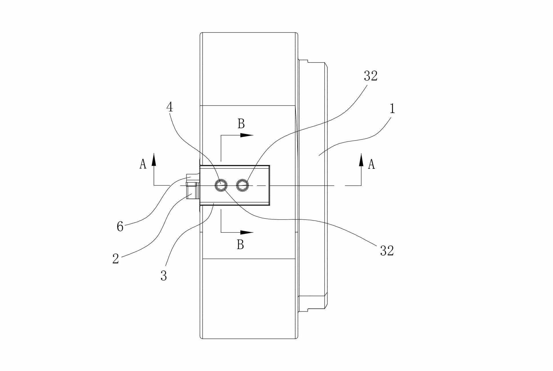
[0022] Figure 1 to Figure 7 A cutting tool embodiment for high-speed cutting of the invention is shown, the cutting tool includes a cutter body 1, and the cutter body 1 is provided with at least one set of sipe grooves 21 with a wedge-shaped cross section, and the number of sipe grooves 21 can be determined according to the specific Depending on the cutting situation, the present embodiment is only provided with one group of sipes 21, which are equipped with toolholders 2, wedges 3 and fasteners 4, and the wedges 3 are provided with a knife with an opening facing the bottom of the sipes 21. The clip accommodation groove 31, the tool holder 2 is placed in the tool holder accommodation groove 31, the cutting blade 6 is installed on the tool holder 2, and the threaded hole 22 corresponding to the fastener 4 is provided, and the fastener 4 is threaded on the In the threaded hole 22 of the tool holder 2, the head 41 of the fastener 4 is pushed against the bottom surface of the too...


PUM


Abstract

The invention discloses a cutting tool for high-speed cutting, comprising a cutter body. At least one group of cutter grooves with wedge-shaped cross sections are arranged on the cutter body, a cutter holder, a wedge block and a fastening piece are arranged in the cutter grooves, a cutter holder containing groove with an opening towards to the bottom surface of the cutter groove and a fastening piece adjusting hole corresponding to the head part of a fastening piece are arranged on the wedge block, the cutter holder is arranged in the cutter holder containing groove, the fastening piece is inthreaded connection with the cutter holder, the head part of the fastening piece pushes against the bottom surface of the cutter holder containing groove, the wedge block and the cutter groove are tightly matched under the pushing-against action of the fastening piece, and the cutter holder is pressed and fixed on the bottom surface of the cutter groove. The cutting tool for high-speed cutting has the advantages of simple and compact structure, low production cost and high safety coefficient, and being convenient to process and manufacture.

Description

technical field [0001] The invention relates to the field of metal cutting, in particular to a cutting tool for high-speed cutting. Background technique [0002] During the cutting process of rotary cutting tools, high-speed cutting (cutting speed between 1000m / min and 5000m / min) can greatly improve the processing efficiency and improve the quality of the processed surface. Due to the high density of ordinary cutting tool materials (generally steel), during high-speed cutting, especially when the outer diameter of the cutting tool exceeds Φ100mm, the tool greatly increases the spindle rotation load when the machine tool is started. In order to reduce the rotation load of the spindle of the machine tool, aluminum alloys with low density are generally used as tool materials, but the bending strength of aluminum alloys is only 1 / 4 to 1 / 2 of that of ordinary cutting tool materials. The cutting edge and the surrounding clamping parts will generate a large centrifugal force. Usin...

Claims


Application Information

Patent Timeline
Patent Type & Authority Applications(China)
IPC IPC(8): B23Q3/00
Inventor 刘敏江爱胜
Owner ZHUZHOU CEMENTED CARBIDE CUTTING TOOLS CO LTD
Learn More