Variable speed scooter

A scooter, body technology, applied in the direction of vehicle gearbox, vehicle parts, chain/belt transmission device, etc., can solve the problems of difficulty in climbing, large pedaling force, large movement angle, etc., and achieves fast leveling speed and easy shifting process. , to meet the effect of uphill power

Active Publication Date: 2011-09-14
佛山市苏普尔科技有限公司
View PDF11 Cites 6 Cited by
  • Summary
  • Abstract
  • Description
  • Claims
  • Application Information

AI Technical Summary

Problems solved by technology

[0006] But the scooter of several disclosed repetitive trampling motions has heavy starting (or stepping on a large stroke, causing a large angle of motion), large stepping force in motion, and people's feet are prone to acid and fatigue in a short period of time. There are no structural labor-saving and speed-changing effects, making it difficult to go uphill.

Method used


Image

  • Variable speed scooter
  • Variable speed scooter
  • Variable speed scooter

Examples


Embodiment 1

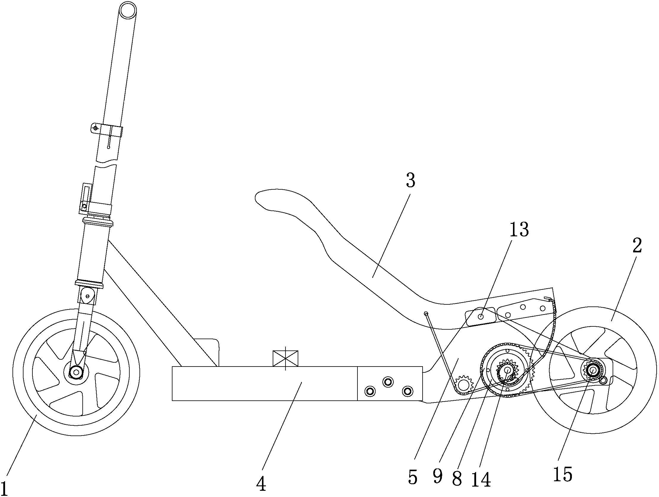
[0075] See figure 1 and figure 2 , a variable speed scooter, comprising a vehicle body, a front wheel 1, a rear wheel 2 and a drive system, the vehicle body includes a power lever 3 and a body bracket, the body bracket includes a main bracket 4 and a power fixing piece 5, and the power fixing piece 5 is provided with an upper power The rotating shaft 13 , the front power rotating shaft 14 and the rear power rotating shaft 15 , and the power lever 3 are arranged on the upper power rotating shaft 13 . This embodiment is a single power output structure, the number of the drive system is one, the number of the power lever 3 is one, the drive system is arranged on the right side of the vehicle body support, the drive system is connected to the power lever 3, and the power lever 3 is from opening to closing , has a power output; the power lever 3 returns from closing to opening, and has no power output.

[0076] The drive system includes a power system and a return system. The po...

Embodiment 2

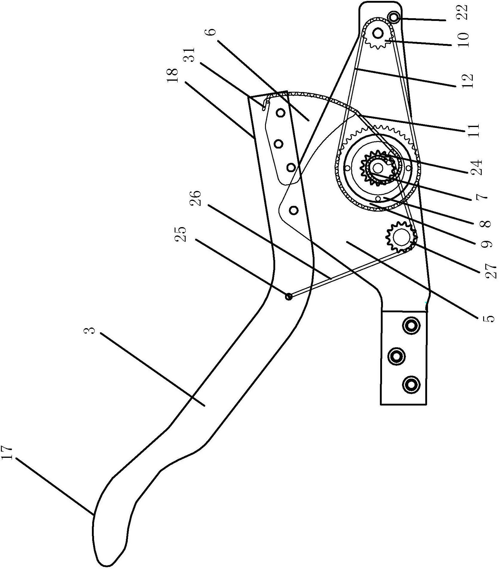
[0093] The difference between this embodiment and Embodiment 1 is that this embodiment adopts a return system of another structure, the return system includes a return gear 24 and a return spring 28, and the return gear 24 is sleeved on the front One end of the power shaft 14 and the return spring 28 are fixed to the main bracket 4 , and the other end of the return spring 28 is connected to the return gear 24 through the return chain 26 . Such as Figure 18 As shown, when the power lever 3 is in the open state, the return spring 28 is in the pre-tension state, and when the front end stepping point 17 of the power lever 3 is stepped down, the sprocket 6 moves upward, and the eccentric is pulled by the sprocket chain 11 The wheel 7 turns counterclockwise, and since the eccentric wheel 7 and the return gear 24 both fix the front power rotating shaft 14, the return gear 24 also rotates counterclockwise with it, thereby pulling the return chain 26, so that the return spring 28 is o...

Embodiment 3

[0095] Such as Figure 19 and Figure 20 , this structure is one of the dual power output structures. The number of drive systems in this embodiment is two, and the number of power levers 3 is two. The two drive systems are respectively arranged on the left and right sides of the vehicle body bracket. The drive system on the side is connected to the power lever 3 on the left side, and the drive system on the right side is connected to the power lever 3 on the right side. In this embodiment, the power lever 3 on the left side and the power lever 3 on the right side rotate alternately around the power shaft 13 at the same time, and only two feet need to be placed on the front end stepping point 17 of the power lever 3 on the left side and on the right side respectively. Stepping on the front end stepping point 17 of the power lever 3 of the power lever 3 on the left side and the power lever 3 on the right side move up and down, so that the left and right power systems are in th...


PUM


Abstract

The invention relates to the technical field of scooters, in particular to a variable speed scooter. The variable speed scooter comprises a scooter body, a front wheel, a rear wheel and a driving system, wherein the scooter body comprises a power lever and a scooter body bracket; the scooter body bracket is provided with an upper power spindle, a front power spindle and a rear power spindle; the power lever is arranged on the upper power spindle; the driving system comprises a power system and a returning system; the power system comprises an eccentric wheel and a gear driving system, the eccentric wheel is arranged on the front power spindle; the front power spindle is driven to be connected with the rear power spindle by the gear driving system; the power lever is driven to be connected to the eccentric wheel; and the rear wheel is arranged on the rear power spindle. According to the eccentric wheel, the variable speed scooter saves power and has simple variable speed process, and different speeds can be realized by changing a treading travel angle, thereby satisfying the requirements of large upslope power and high flat ground speed.

Description

technical field [0001] The invention relates to the technical field of scooters, in particular to a variable-speed scooter. Background technique [0002] The scooter can be used as an entertainment product for children and adults in their leisure time, a means of transportation for people to travel at close distances, fitness equipment, etc. , easy to learn, suitable for multi-level fields and people of many ages to use and so on. [0003] The Chinese utility model patent No. 97230502.5 introduces a pedal skateboard, which is composed of a seesaw, a bracket, a wire rope, a flywheel, a guide pulley, and front and rear wheels. The wire ropes installed at both ends of the seesaw are connected with the flywheel through guide pulleys. When the seesaw moves up and down, the wire rope drives the flywheel to rotate, and the rear wheel slides forward in conjunction with the rear wheel. [0004] The Chinese Utility Model Patent No. 01237990.5 introduces a driving device for a scoot...

Claims


Application Information

Patent Timeline
Patent Type & Authority Applications(China)
IPC IPC(8): B62M1/04B62M9/04B62M1/24
Inventor 李建和
Owner 佛山市苏普尔科技有限公司
Why Eureka
Try Eureka