
Measuring device adopting solid-state vibration angular rate sensor group to realize north-seeking underground

An angular rate sensor, solid-state vibration technology, used in surveying, earthmoving, wellbore/well components, etc., can solve problems such as low accuracy and reliability, limited methods and means, and high cost

Active Publication Date: 2011-09-14
CHONGQING UNIV OF POSTS & TELECOMM +1
View PDF4 Cites 4 Cited by
  • Summary
  • Abstract
  • Description
  • Claims
  • Application Information

AI Technical Summary

Problems solved by technology

[0007] The azimuth measurement while drilling has almost limit requirements on the working conditions of the instrument, so that most of the angular rate sensors that are not suitable for azimuth measurement while drilling are limited. All mechanical angular rate sensors with moving parts and dynamic tuning angular rate sensors have In theory, it has exceeded the design requirements in terms of anti-shock and vibration, and it is impossible to realize the azimuth measurement while drilling
From this point of view, the methods and means of using inertial devices for geosteering measurement while drilling are very limited, and the developed countries of foreign logging technology have not developed a more suitable angular rate sensor while drilling, but have adopted no angular rate sensor to measure Even non-inertial device geosteering while drilling survey method, but the accuracy and reliability are not high, and the cost is quite expensive

Method used


Image

  • Measuring device adopting solid-state vibration angular rate sensor group to realize north-seeking underground
  • Measuring device adopting solid-state vibration angular rate sensor group to realize north-seeking underground
  • Measuring device adopting solid-state vibration angular rate sensor group to realize north-seeking underground

Examples


Embodiment Construction

[0023] Due to the complexity of the measurement environment in petroleum and geological drilling, it is a challenging task to use solid-state vibration angular rate sensors to measure azimuth and drilling tools to perform measurement while drilling. For example, a measurement tool will experience an acceleration shock along the direction of the sensitive axis of the angular velocity measurement. Because solid-state vibration angular rate sensor errors are a function of sensitive acceleration, small accelerations can also cause large angular rate errors. Vibration can cause fluctuations in the output of solid-state vibration angular rate sensors, leading to increased random errors. In addition, because the solid-state vibration angular rate sensor uses a feedback loop, high frequency vibration may introduce unnecessary errors.

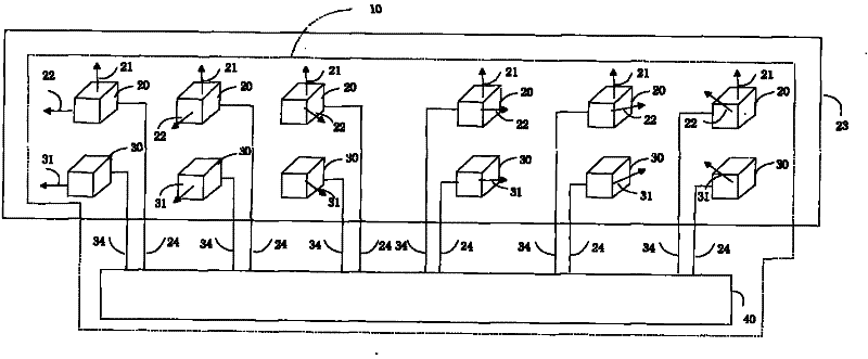
[0024] Such as figure 1 , which is a schematic diagram of the measuring device 10 .

[0025] Surveying device 10 may be used as part of inertial mea...


PUM


Abstract

The invention relates to a measuring device adopting a solid-state vibration angular rate sensor group to realize north-seeking underground while drilling, comprising a solid-state vibration angular rate sensor group for conducting vertical shaft measurement, a solid-state vibration angular rate sensor group for conducting horizontal shaft measurement as well as an accelerometer group. The measuring device is characterized in that accelerometers and solid-state vibration angular rate sensors in the solid-state vibration angular rate sensor group and the accelerometer group are arranged correspondingly; the minimum acceleration sensitive direction of each solid-state vibration angular rate sensor and the sensitive direction of each accelerometer in the horizontal direction misplace by a same angle in sequence in the range of 360 degrees, sensitive shafts of the solid-state vibration angular rate sensors are mutually horizontal, each solid-state vibration angular rate sensor can generate an angular velocity along the sensitive shaft, and each accelerometer detects and outputs an acceleration along the sensitive direction; and a controller completes the selection of a certain drilling direction, and conducts digital weight integration and calculation to a measurement signal. The device meets the high measurement precision while reducing the cost.

Description

technical field [0001] The invention mainly relates to a drilling measurement device, specifically a device composed of a solid-state vibration angular rate sensor group, which adopts an acceleration-assisted weight distribution algorithm to improve the measurement accuracy of the angular rate sensor, thereby realizing azimuth measurement while drilling. Background technique [0002] Well logging technology is a science and technology that arose and developed along with the petroleum industry, and it is a kind of downhole oil and gas exploration technology. Well logging is a technique for measuring, recording, and analyzing the physical properties of downhole rock or fluid during oil and gas exploration and development, and for oil and gas evaluation of reservoirs. Its application is mainly concentrated in two fields: formation evaluation and well completion evaluation, with only one purpose, which is to find oil and gas deposits, evaluate oil and gas reserves and their prod...

Claims


Application Information

Patent Timeline
IPC IPC(8): E21B47/02
Inventor 刘宇曾燎燎迈克尔欧毅路永乐段耀宇刘申刘俊
Owner CHONGQING UNIV OF POSTS & TELECOMM
Learn More