Transmission with three shafts and two clutches

A dual-clutch and transmission technology, applied to gear transmissions, elements with teeth, belts/chains/gears, etc., can solve problems such as large frictional resistance and reduced transmission efficiency of transmissions, so as to improve reliability and reserve space The effect of reducing and improving efficiency

Active Publication Date: 2011-09-14
ZHEJIANG WANGLIYANG TRANMISSION CO LTD
View PDF5 Cites 13 Cited by
  • Summary
  • Abstract
  • Description
  • Claims
  • Application Information

AI Technical Summary

Problems solved by technology

However, the master and driven friction plates of the multi-plate clutch in the disengaged state slip through each other due to the lubricating oil, resulting in relatively large frictional resistance, which reduces the transmission efficiency of the transmission accordingly.

Method used


Image

  • Transmission with three shafts and two clutches
  • Transmission with three shafts and two clutches
  • Transmission with three shafts and two clutches

Examples


Embodiment 1

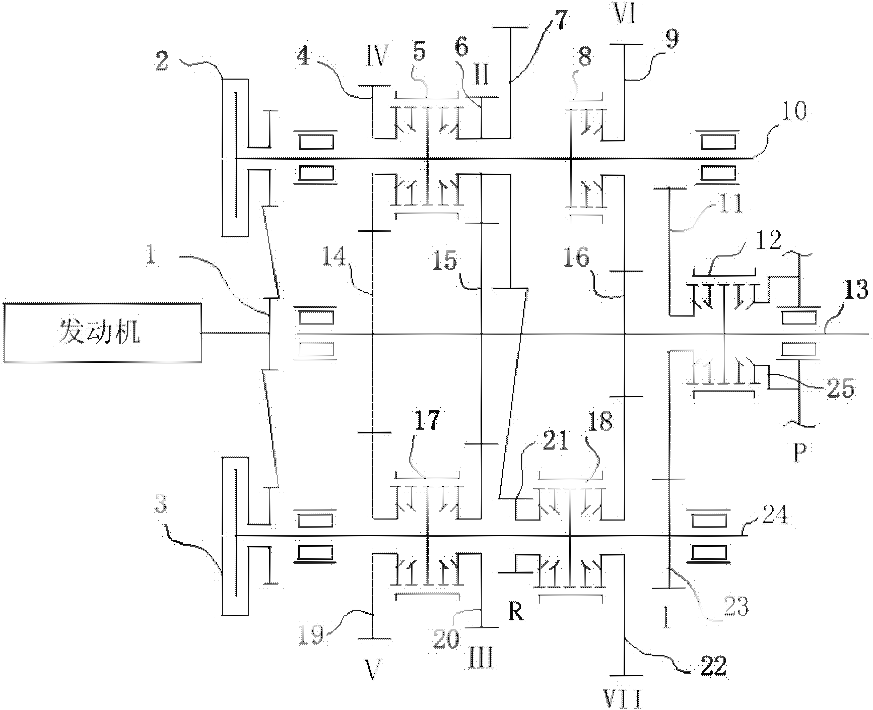
[0018] Such as figure 1 As shown, the first gear driving gear 23, the third gear driving gear 20, the fifth gear driving gear 19, the seventh gear driving gear 22 and the reverse gear driving gear 21 of the odd-numbered driving gear set are arranged on the first input shaft 24; The second gear driving gear 6, the fourth gear driving gear 4, the sixth gear driving gear 9 and the reverse driven gear 7 of the driving gear set are arranged on the second input shaft 10; the fifth gear driving gear 19 and the third gear driving gear 20 are formed by the second gear A synchronous device 17 is connected, the reverse gear driving gear 21 is connected with the seventh gear driving gear 22 by the second synchronizing device 18, the fourth gear driving gear 4, the second gear driving gear 6 and the reverse gear driven gear 7 are connected by the third synchronizing device 5 , the sixth gear driving gear 9 is connected to the fourth synchronizing device 8, and the first driven gear 11, the...

Embodiment 2

[0031] The drive gear 1 located on the main shaft of the engine rotates together with the engine. The driving side / driven side of two clutches (the first clutch 3 and the second clutch 2 ) are driven, and the driven side / driving side of the two clutches are respectively connected to corresponding input shafts. Two input shafts are arranged in parallel at a certain distance, namely the first input shaft 24 and the second input shaft 10 .

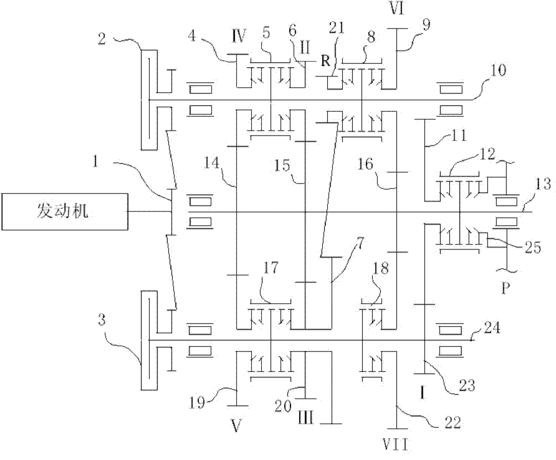
[0032] The first gear driving gear 23, the third gear driving gear 20, the fifth gear driving gear 19, the seventh gear driving gear 22 and the reverse driven gear 7 of the odd-numbered gear group are arranged on the first input shaft 24; The second gear driving gear 6, the fourth gear driving gear 4, the sixth gear driving gear 9 and the reverse gear driving gear 21 of the group are arranged on the second input shaft 10; the fifth gear driving gear 19 and the third gear driving gear 20 are controlled by the first synchronizing device 17 con...


PUM


Abstract

The invention belongs to transmissions, in particular relates to a transmission with three shafts and two clutches. The transmission with three shafts and two clutches is characterized by comprising the two clutches, two input shafts and one output shaft; the two clutches are driven by an engine in a gear driving or belt driving manner and are respectively connected with the corresponding input shafts; a drive gear set with odd gears is arranged on one input shaft, while drive gear sets with even gears are arranged on the other input shaft; a driven gear set is arranged on the output shaft; the drive gears of the two input shafts share a corresponding driven gear; a drive gear of a reverse gear is arranged on one input shaft; a driven gear of the reverse gear is arranged on the other input shaft and meshed with the drive gear of the reverse gear; a joint gear ring of a parking mechanism is fixedly connected with a box and matched with a synchronous device of the output shaft; and a parking function is realized by pulling a shifting fork by a gear shifting pull wire. The transmission with three shafts and two clutches is compact in structure and low in cost; besides, the transmission does not employ a concentric shaft, therefore, the axial length of the transmission is reduced, the rigidity of the system is enhanced, and the performance is reliable.

Description

technical field [0001] The invention belongs to the category of transmissions, in particular to a three-shaft double-clutch transmission. Background technique [0002] The dual-clutch transmission realizes the shifting action through the matched switching of the two clutches, and the shifting is fast and smooth. During the shifting process, the power of the engine is continuously transmitted to the wheels to realize power shifting and ensure that the vehicle has good acceleration performance. The dual-clutch transmission is developed based on the parallel-shaft manual transmission, and it inherits many advantages of the manual transmission, such as high transmission efficiency, compact installation space, light weight, and low price. [0003] At present, there are mainly three types of dual-clutch transmission structures: dual-clutch single-shaft output, combined clutch single-shaft output and combined clutch dual-shaft output. The dual-clutch single-shaft output maximizes...

Claims


Application Information

Patent Timeline
Patent Type & Authority Applications(China)
IPC IPC(8): F16H3/087
CPCF16H63/3416F16H3/006
Inventor 孙伟陈德民夏伟强麻越垠王涛郭晓林史小飞陆晓平任华林张晓聪
Owner ZHEJIANG WANGLIYANG TRANMISSION CO LTD
Why Eureka
Try Eureka