Thick grease secondary lubricating pump device

A lubricating pump and grease technology, which is applied in the field of lubrication, can solve problems such as difficulty in effective pumping, small opening of oil suction port, and reduced service performance and life of machinery and equipment, achieving high pumping grease capacity and expanding the scope of application

Active Publication Date: 2011-09-14
AUTOL TECH
View PDF2 Cites 81 Cited by
  • Summary
  • Abstract
  • Description
  • Claims
  • Application Information

AI Technical Summary

Problems solved by technology

For example, LINCOLN series plunger pumps, VOGEL series plunger pumps, BIJUR series plunger pumps, etc. already on the market, basically meet the filling requirements of various types of machinery using oil with low viscosity when running at room temperature. However, for mechanical equipment that requires high-viscosity grease and operates normally in low-temperature environment or low-pressure environment in winter, such as the northern winter climate environment, it is difficult for the current plunger pump to pump ordinary NLGI2# grease effectively. The reason is that these plunger pumps that rely on the suction of the oil suction port to suck grease have a small opening at the suction port, and the vacuum suction formed by the oil suction at the oil suction port is also small.
Therefore, at present, for most mechanical equipment that requires high-viscosity grease and operates normally in a low-temperature environment or low-pressure environment in winter, it is either lubricated by a manual grease gun, or the use of low-viscosity grease is required to reduce friction pair lubrication. , which will reduce the performance and life of machinery and equipment, and affect the operation

Method used


Image

  • Thick grease secondary lubricating pump device
  • Thick grease secondary lubricating pump device
  • Thick grease secondary lubricating pump device

Examples


Embodiment Construction

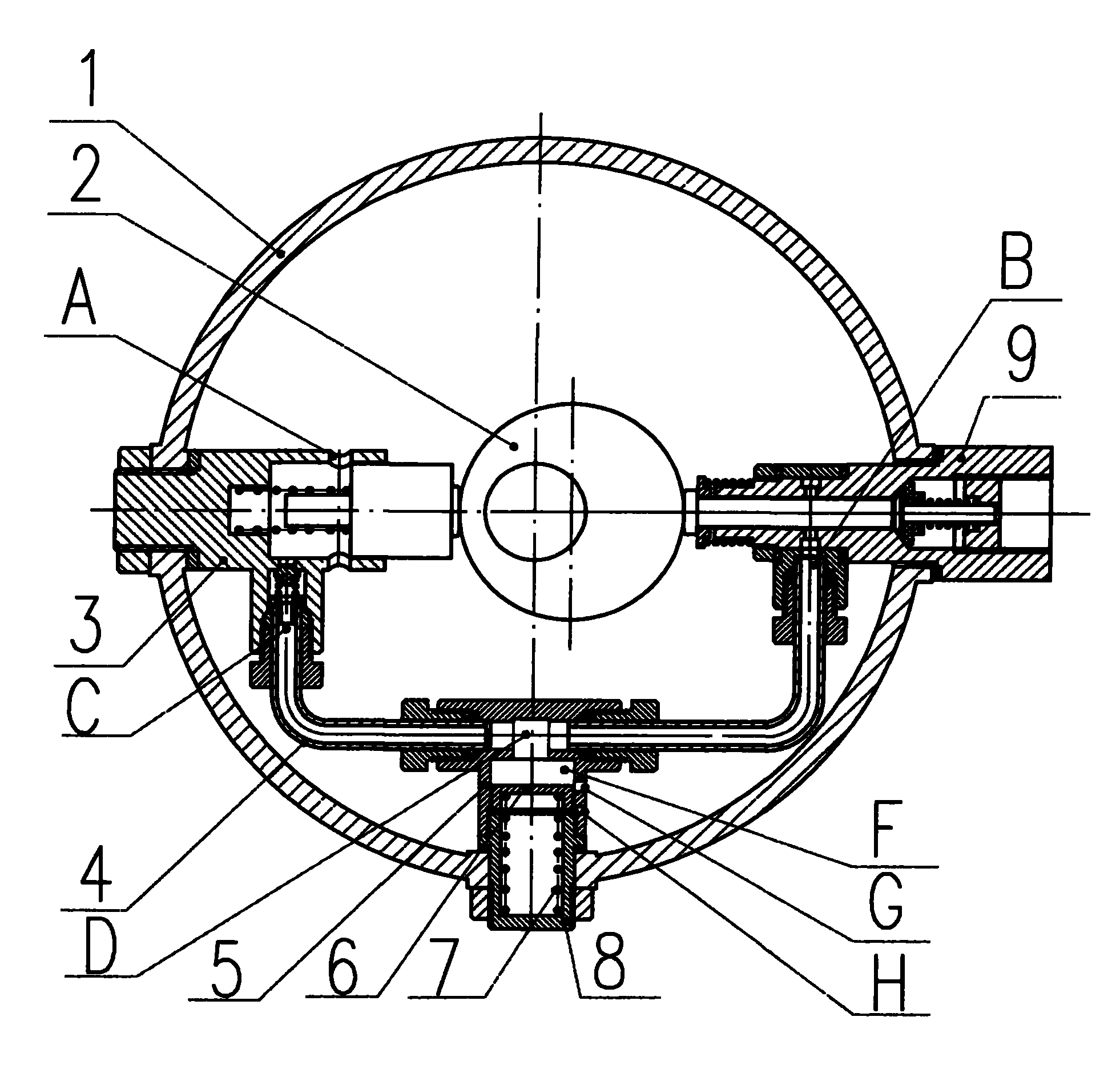
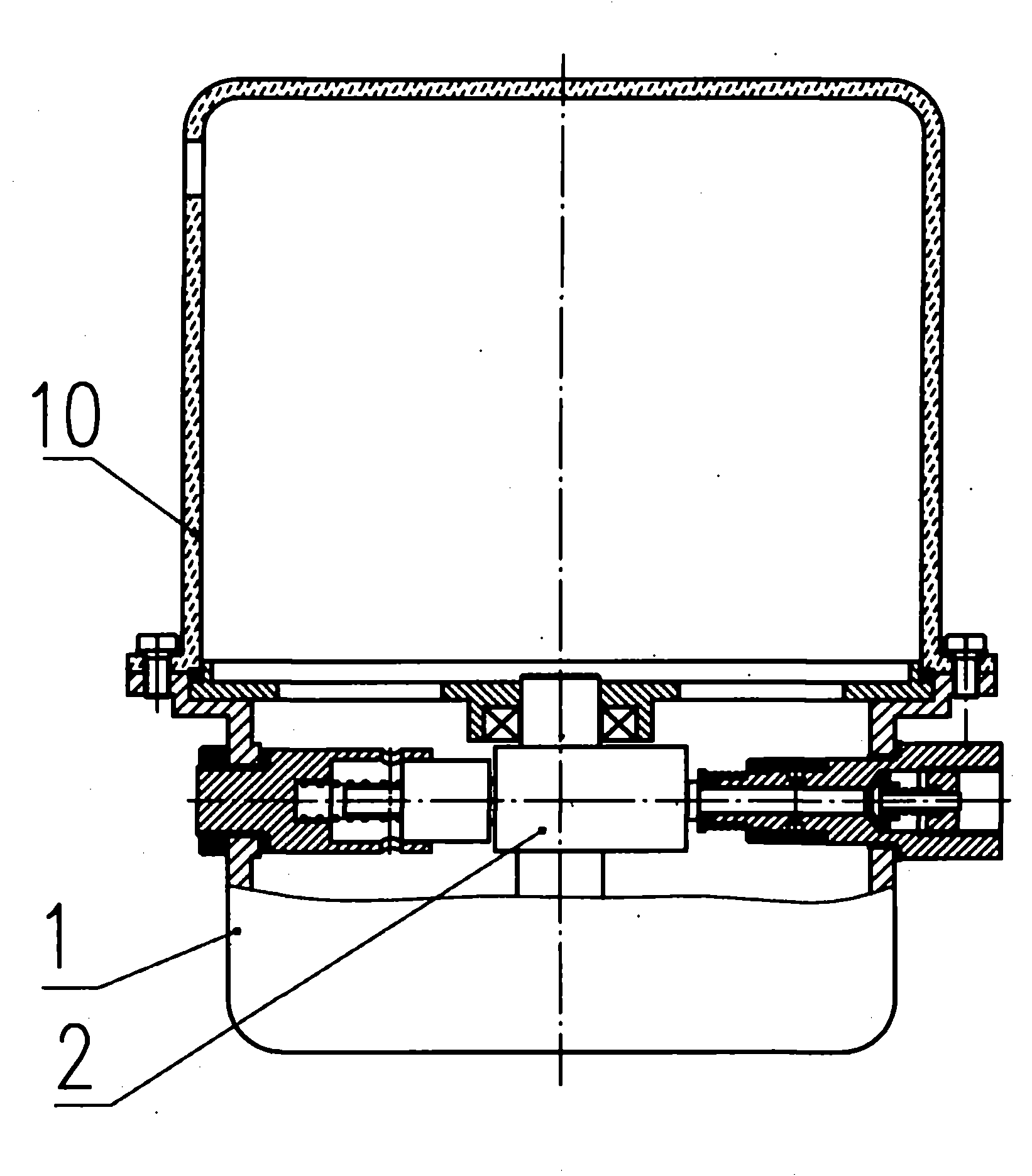
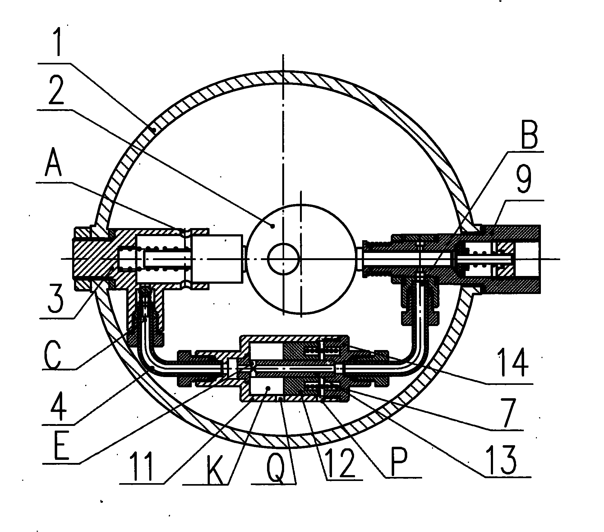
[0013] The present invention is further described below by accompanying drawing. figure 1 with figure 2 In the schematic diagram of the structure of the viscous grease two-stage lubrication pump device shown, the power assembly 2 used to provide power and drive the operation of the lubrication pump and the high-pressure plunger pump 9 driven by it are installed on the lubrication pump housing 1, and the oil tank 10 It is fixedly connected with the lubricating pump housing 1. The lubricating pump housing 1 is also equipped with a low-pressure plunger pump 3 driven by the power assembly 2. The oil suction port A of the low-pressure plunger pump 3 is connected to the oil tank 10, and its oil discharge port C is connected to the oil tank. The oil suction port B of the high-pressure plunger pump is sealed and connected through a pipeline 4, and an accumulator is connected to the pipeline 4, and the oil inlet and outlet of the accumulator are respectively connected to the oil disch...


PUM


Abstract

A thick grease secondary lubricating pump device comprises a lubricating pump shell, a power assembly, a high-pressure plunger pump and an oil tank, wherein the power assembly and the high-pressure plunger pump driven by the power assembly are arranged on the lubricating pump shell; the oil tank is fixedly connected with the lubricating pump shell which is also provided with a low-pressure plunger pump driven by the power assembly; an oil suction port A of the low-pressure plunger pump is communicated with the oil tank, and an oil discharge port C of the low-pressure plunger pump is connectedwith an oil suction port B of the high-pressure plunger pump in a sealing way by a pipeline which is further connected with an energy storage device and an overflow valve; and an oil inlet and an oiloutlet of the energy storage device are respectively communicated with the oil discharge port C of the low-pressure plunger pump and the oil suction port B of the high-pressure plunger pump. By adopting the structure, the lower-pressure plunger pump with the section of a first-stage oil inlet being larger is added, enough grease is pressed into an oil inlet of the high-pressure plunger pump, and the mode that mainly depends on the oil suction of the oil inlet of high-pressure plunger pump is changed to the mode mainly depending on pressing the oil, so that the oil charging at the oil inlet ofthe high-pressure plunger pump is sufficient, the capacity of the pump for delivering the grease is enhanced, and the pump is capable of delivering the grease with high thickness even under low temperature and low pressure.

Description

technical field [0001] The invention belongs to the technical field of lubrication, and relates to a lubrication pump device, in particular to a viscous grease secondary lubrication pump device. Background technique [0002] At present, centralized grease lubrication technology has been widely used in our country. It can implement timing and quantitative automatic oil injection to each lubrication point when the mechanical equipment is running. This type of device overcomes the shortcomings of manual oiling. For example, LINCOLN series plunger pumps, VOGEL series plunger pumps, BIJUR series plunger pumps, etc. already on the market, basically meet the filling requirements of various types of machinery using oil with low viscosity when running at room temperature. However, for mechanical equipment that requires high-viscosity grease and operates normally in low-temperature environment or low-pressure environment in winter, such as the northern winter climate environment, it ...

Claims


Application Information

Patent Timeline
Patent Type & Authority Applications(China)
IPC IPC(8): F16N13/06
Inventor 赵大平马利峰
Owner AUTOL TECH
Why Eureka
Try Eureka