
Method and device for detecting contrast ratio of bright and dark regions of hidden image in anti-counterfeiting element

A technology of anti-counterfeiting components and contrast, applied in the field of anti-counterfeiting, can solve the problems of inability to realize the quality of anti-counterfeiting components, unable to quantitatively judge the quality of anti-counterfeiting components, etc., and achieve the effect of accurate control and objective evaluation standards

Inactive Publication Date: 2012-11-14
SECURITY PRINTING INST OF PEOPLES BANK OF CHINA +1
View PDF0 Cites 0 Cited by
  • Summary
  • Abstract
  • Description
  • Claims
  • Application Information

AI Technical Summary

Problems solved by technology

[0005] At present, it is only possible to qualitatively detect the contrast between the bright and dark areas of the positive and negative images hidden by the anti-counterfeiting components manually. During detection, the observer uses a polarizer to observe the positive and negative images hidden by the anti-counterfeiting component, and rotates the polarizer 90 degrees to detect Realize the switching between positive and negative films, and judge the contrast between the light and dark areas of the positive and negative film images hidden by the anti-counterfeiting element by comparing the clarity of the positive and negative images, because different observers have different perceptions of color and light and shade , affected by the subjectivity of artificial vision, it is impossible to quantitatively judge the quality of anti-counterfeiting components, therefore, it is impossible to achieve precise and accurate control of the quality of anti-counterfeiting components

Method used

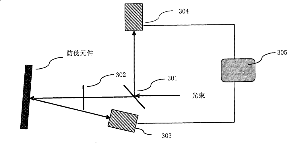

Image

  • Method and device for detecting contrast ratio of bright and dark regions of hidden image in anti-counterfeiting element
  • Method and device for detecting contrast ratio of bright and dark regions of hidden image in anti-counterfeiting element
  • Method and device for detecting contrast ratio of bright and dark regions of hidden image in anti-counterfeiting element

Examples


Embodiment Construction

[0029] The following will clearly and completely describe the technical solutions in the embodiments of the present invention with reference to the accompanying drawings in the embodiments of the present invention. Obviously, the described embodiments are only some, not all, embodiments of the present invention. Based on the embodiments of the present invention, all other embodiments obtained by persons of ordinary skill in the art without creative efforts fall within the protection scope of the present invention.

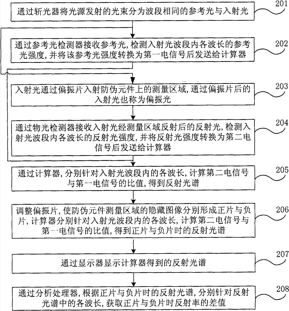
[0030] figure 1 It is a flow chart of an embodiment of the method for detecting the contrast between light and dark areas of an image hidden by an anti-counterfeit element according to the present invention. Such as figure 1 As shown, the detection method of this embodiment includes the following processes:

[0031] Step 101, the incident light enters the measurement area on the anti-counterfeiting element through the polarizer.

[0032] In particular, the measu...


PUM


Abstract

The invention discloses a method and device for detecting a contrast ratio of bright and dark regions of a hidden image in an anti-counterfeiting element. The method comprises the following steps of: enabling incident light to enter a measurement region on the anti-counterfeiting element through a polaroid; adjusting the polaroid to ensure that the hidden image in the anti-counterfeiting element respectively forms a positive polaroid and a negative polaroid and measuring a reflectance spectrum of the measured region when in the positive polaroid and the negative polaroid, wherein the reflectance spectrum indicates the reflectivity of each wavelength in the incident optical band; and acquiring a difference value or a ratio value of the reflectivity when in the positive polaroid and the negative polaroid by respectively aiming at each wavelength in the reflectance spectrum according to the reflection spectrum when in the positive polaroid and the negative polaroid so that the contrast ratio of the bright and dark regions of the hidden image in the anti-counterfeiting element can be determined according to the difference value or the ratio value. The method and device disclosed by the embodiment of the invention realize the quantitive detection of the contrast ratio of the bright and dark regions of the hidden positive and negative polaroid image of the anti-counterfeiting element, thereby realizing the precise and accurate control over the quality of the anti-counterfeiting element.

Description

technical field [0001] The invention relates to anti-counterfeiting technology, in particular to a method and device for detecting the contrast between light and dark areas of images hidden by anti-counterfeiting components. Background technique [0002] At present, in the field of anti-counterfeiting technology, liquid crystal optically variable anti-counterfeiting components with hidden positive and negative film information produced by liquid crystal technology are favored because of their second-line anti-counterfeiting features such as hiding fine graphics and realizing positive and negative film conversion. When the anti-counterfeiting element is placed under the polarizer, its hidden positive and negative images can be observed, that is: fine graphics. Adjust the angle between the polarizer and the anti-counterfeiting element. When the positive and negative images hidden by the anti-counterfeiting element present the brightest and darkest areas, all the dark areas pre...

Claims


Application Information

Patent Timeline
Patent Type & Authority Patents(China)
IPC IPC(8): G01M11/02G01J3/42G02B5/30
Inventor 王斌陈庚柯光明周基炜刘卫东
Owner SECURITY PRINTING INST OF PEOPLES BANK OF CHINA
Learn More