
Arrayed waveguide grating wavelength division multiplexer

An arrayed waveguide grating and wavelength division multiplexer technology, which is applied in the field of optical transmission, can solve the problems of phase error, influence, and AWG wavelength polarization correlation channel crosstalk deterioration, etc., and achieves the effect of low miniaturization

Inactive Publication Date: 2011-09-14
GUANGXUN SCI & TECH WUHAN
View PDF3 Cites 14 Cited by
  • Summary
  • Abstract
  • Description
  • Claims
  • Application Information

AI Technical Summary

Problems solved by technology

If a curved waveguide with air slots is used on its array waveguide, it will be easier to affect the phase of its array waveguide, resulting in phase error, and this kind of waveguide with high refractive index difference, because the air on both sides, its refractive index is relative to the waveguide layer Much smaller, generally polarization sensitive, so it will lead to poor wavelength polarization dependence of AWG and crosstalk between channels

Method used


Image

  • Arrayed waveguide grating wavelength division multiplexer
  • Arrayed waveguide grating wavelength division multiplexer
  • Arrayed waveguide grating wavelength division multiplexer

Examples


Embodiment Construction

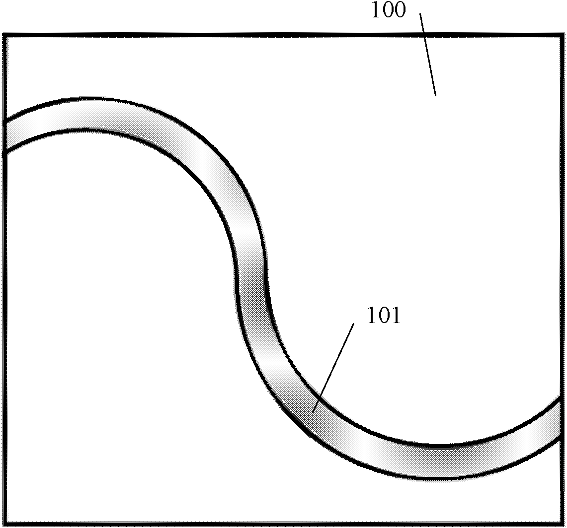
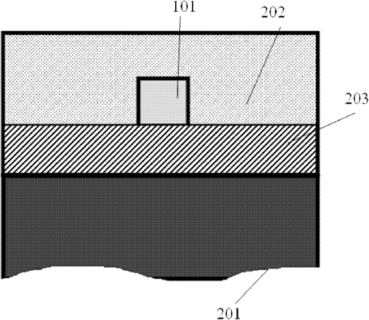
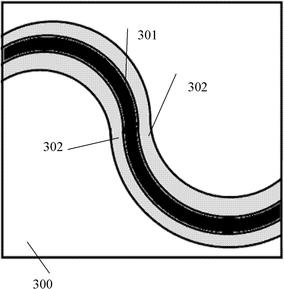
[0024] As a whole, the size of the optimized chip can be considered from the following aspects: reducing the input slab waveguide and the output slab waveguide so as to reduce the chip size. The present invention reduces the distance between the output waveguide and the connection of the output slab waveguide by making the part of the input waveguide / output waveguide connected to the slab waveguide into a high refractive index waveguide with air grooves on both sides, so as to ensure the uniformity of insertion loss. Under the premise of all optical indicators such as , crosstalk, and bandwidth, the size of the input slab waveguide and the output slab waveguide are reduced, thereby reducing the number of array waveguides, thereby greatly reducing the size of the AWG chip.

[0025] The structure of the waveguide multiplexer / demultiplexer of the present invention is as follows Image 6 as shown, Image 6 It is an AWG made of silicon-based silica waveguide with low refractive in...


PUM


Abstract

The invention relates to wavelength division multiplexing technology in the field of light transmission, in particular to an AWG (arrayed waveguide grating) wavelength division multiplexer, which comprises an input waveguide, an input planar waveguide, an arrayed waveguide and an output slab waveguide, and an output waveguide which are connected in sequence, wherein the sections of the input waveguide and the output waveguide respectively comprise a core layer and a covering layer covering the core layer, and the refractive index of the core layer is larger than that of the covering layer. The differences are that one end of the output waveguide, which is connected with the output slab waveguide, is provided with the output waveguide with an air slot; and the output waveguide with the air slot is a high-refractive index difference waveguide, wherein two sides of the core layer of high-refractive index difference are respectively etched with an air slot. The AWG wavelength division multiplexer has the advantages that the volume is small, the coupling loss between optical fibers is little, the wave length amplitude correlation of AWG is good, and the anti-crosstalk property between channels is excellent.

Description

technical field [0001] The invention relates to wavelength division multiplexing technology in the field of optical transmission, in particular to an arrayed waveguide grating wavelength division multiplexer. Background technique [0002] With the development of optical transmission research, wavelength division multiplexing technology has become an effective means to increase the capacity of communication information. The so-called wavelength division multiplexing refers to combining multiple lights of different wavelengths into the same waveguide or optical fiber for transmission, and demultiplexing is to divide the lights of different wavelengths in the same waveguide or optical fiber into different waveguides or optical fibers according to the wavelength. technology. The key part to realize the wavelength division multiplexing technology is the wavelength division multiplexer. Arrayed Waveguide Grating (AWG) wavelength division multiplexing / demultiplexing (WDM) devices...

Claims


Application Information

Patent Timeline
IPC IPC(8): G02B6/293G02B6/12
Inventor 王文敏刘文
Owner GUANGXUN SCI & TECH WUHAN
Learn More