Automatic stacking mechanism of flaker

A wrapping machine and automatic technology, applied in the field of wrapping machines, can solve the problems of insufficient lamination efficiency and complex structure, and achieve the effects of simple structure, high lamination efficiency and reliable operation

Inactive Publication Date: 2011-09-14
SUZHOU SHIHAO BUILDING MATERIAL NEW TECH ENG
View PDF4 Cites 10 Cited by
  • Summary
  • Abstract
  • Description
  • Claims
  • Application Information

AI Technical Summary

Problems solved by technology

However, this kind of stacking mechanism has a complex structure, and the stacking efficiency is not high enough.

Method used


Image

  • Automatic stacking mechanism of flaker
  • Automatic stacking mechanism of flaker
  • Automatic stacking mechanism of flaker

Examples


Embodiment Construction

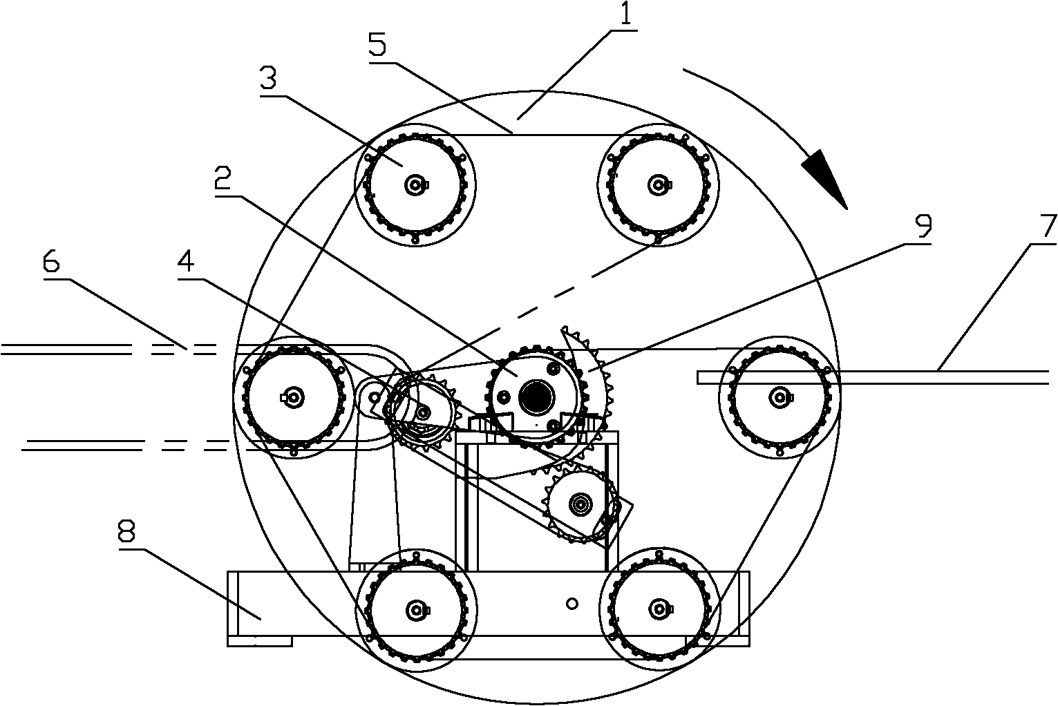
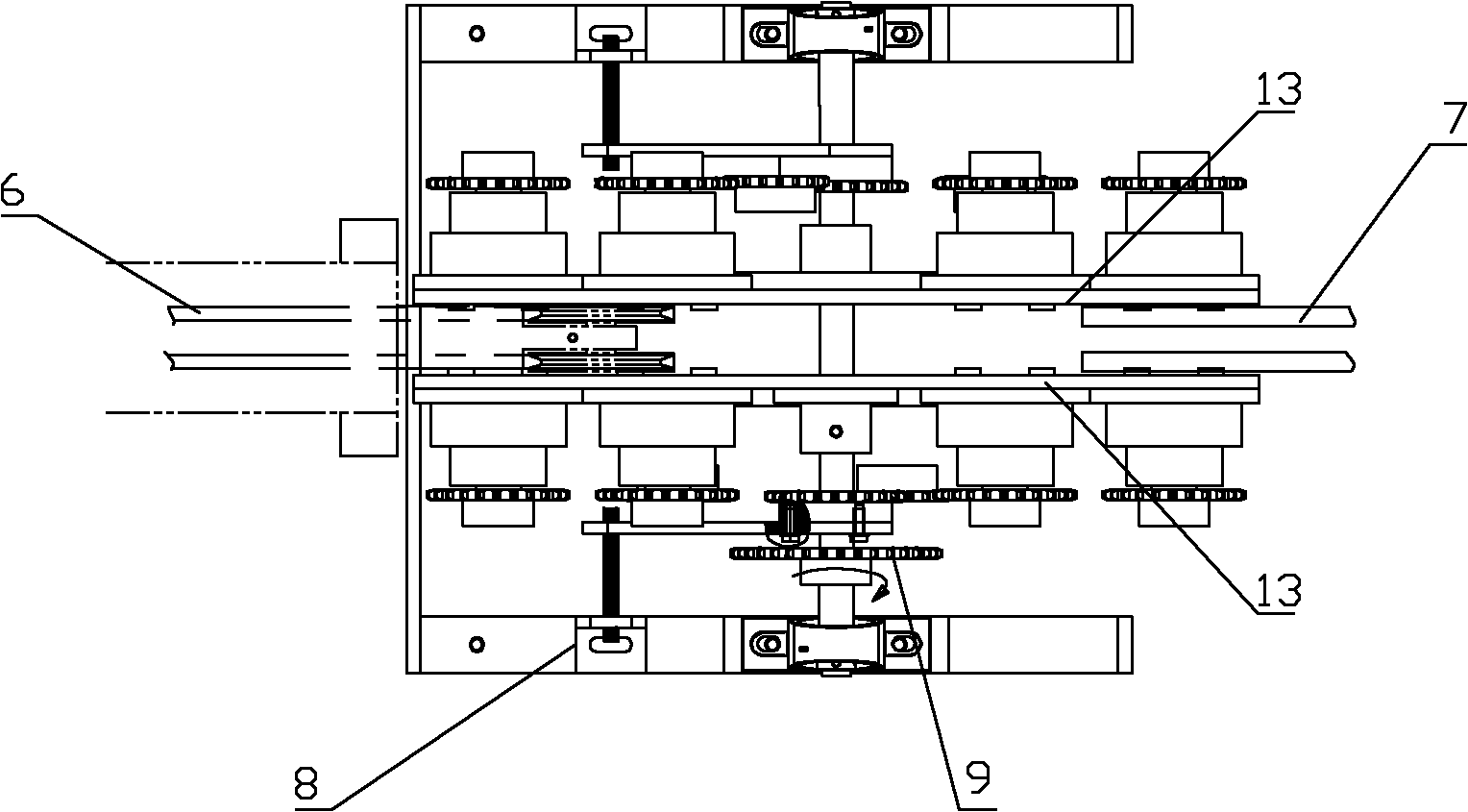
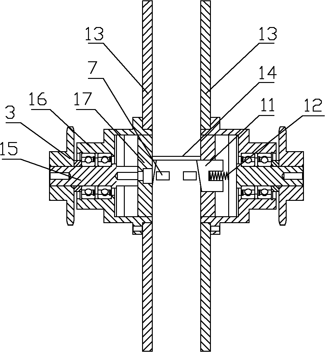
[0018] Such as Figure 1 to Figure 4 As shown, it is the automatic stacking mechanism of the wrapping machine of the present invention, which includes a turntable 1 arranged on a bracket 8, the plane of the turntable is perpendicular to the horizontal plane, and the middle part of the plane of the turntable is provided with a static sprocket 2 that rotates synchronously with the turntable. The outer circle of the plane of the turntable is evenly connected with a number of synchronous sprockets 3 with the stationary sprocket as the center, the number of teeth of the stationary sprocket and the synchronous sprocket is equal, and the synchronous sprocket is connected with a supporting device for supporting the pole plate 14 , the synchronous sprocket and the static sprocket are driven by a chain 5, the left side of the turntable is provided with a conveying device 6 for placing the pole plate on the support device, and the right side of the turntable is provided with a receiving s...


PUM


Abstract

The invention discloses an automatic stacking mechanism of a flaker. The automatic stacking mechanism comprises a turntable arranged on a support, wherein the turntable plane is vertical to the horizontal plane; the middle part of the turntable plane is provided with a static chain wheel which synchronously rotates with the turntable; the excircle of the turntable plane is uniformly and rotatablely connected with a plurality of synchronous chain wheels by taking the static chain wheel as a center; the tooth number of the static chain wheel is equal to that of the synchronous chain wheels; thesynchronous chain wheels are connected with a supporting device for supporting a polar plate; the synchronous chain wheels and the static chain wheel are driven by chains; the left side of the turntable is provided with a conveyor for placing the polar plate onto the supporting device; and the right side of the turntable is provided with a discharging device for receiving the polar plate placed down by the supporting device. Because the automatic stacking mechanism is provided with the turntable, the turntable shaft is provided with the static chain wheel, and the turntable plane is provided with a chain system formed by the synchronous chain wheels and chains, the polar plate on the supporting device connected with the synchronous chain wheels is in a horizontal state, and then the inputpolar plates can be horizontally stacked in turn. The automatic stacking mechanism is simple in structure, reliable in working and high in stacking efficiency.

Description

technical field [0001] The present invention relates to a bagging machine. Background technique [0002] The Chinese utility model whose application number is 200620039126.0 disclosed a lamination mechanism on April 4, 2007, which consists of a stretching cylinder mechanism, a right sprocket mechanism, a left sprocket mechanism, a synchronous transmission mechanism and a bottom plate. The right sprocket mechanism The left sprocket mechanism and the left sprocket mechanism are placed on both sides of the extension cylinder mechanism, connected together by the extension cylinder mechanism, and fixed on the bottom plate symmetrically. The upper and lower passages that can be passed by the cluster composed of flat workpieces, the synchronous transmission mechanism is connected with the right sprocket mechanism and the left sprocket mechanism. It uses a synchronous transmission mechanism to connect with an automatic control system to realize the automation of plate stacking. Ho...

Claims


Application Information

Patent Timeline
Patent Type & Authority Applications(China)
IPC IPC(8): H01M10/04H01M4/04
CPCY02E60/12Y02E60/10Y02P70/50
Inventor 江彪石月明刘艳梨
Owner SUZHOU SHIHAO BUILDING MATERIAL NEW TECH ENG
Why Eureka
Try Eureka