Pneumatic brake cylinder

A pneumatic brake and brake technology, applied in the direction of brakes, brake cylinders, brake components, etc., can solve the problems of high cost, expensive disassembly, difficult installation, etc., and achieve the effect of reducing installation cost and simplifying installation

Active Publication Date: 2011-09-14
KNORR BREMSE SYST FUR SCHIENENFAHRZEUGE GMBH
View PDF6 Cites 13 Cited by
  • Summary
  • Abstract
  • Description
  • Claims
  • Application Information

AI Technical Summary

Problems solved by technology

The force-transmitting connection between the piston and the piston tube results in complex and expensive components, which are difficult to

Method used


Image

  • Pneumatic brake cylinder
  • Pneumatic brake cylinder
  • Pneumatic brake cylinder

Examples


Embodiment Construction

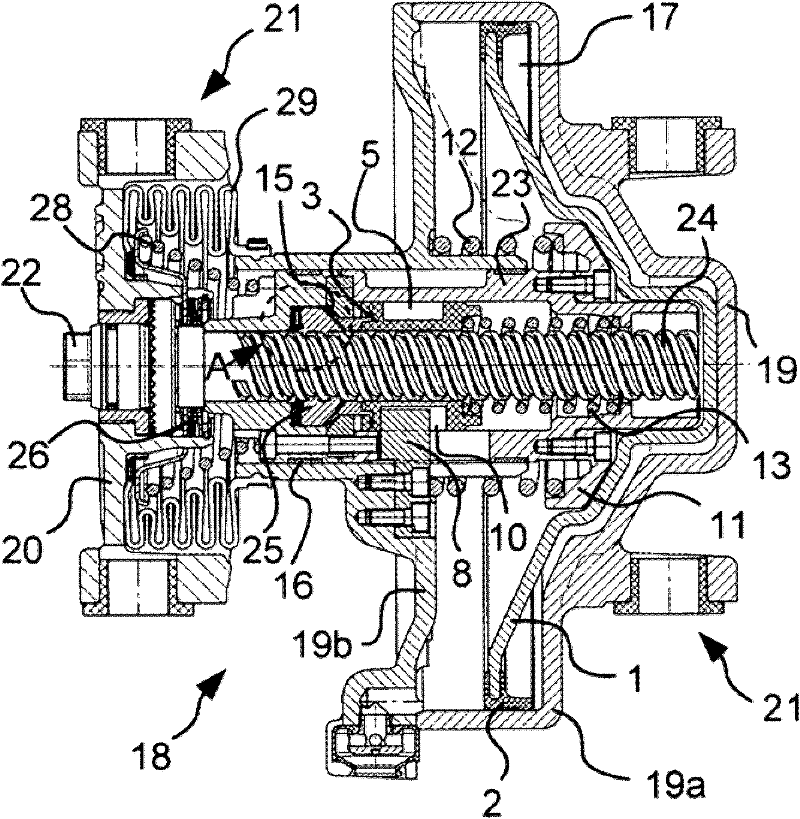
[0028] The fixing device 21 of the brake caliper is located on the one hand on the yoke 20 and on the other hand on the housing 19 assembled from the cylinder 19a and the cover 19b. In order to actuate the brake, the brake calipers (not shown here) have to be pressed apart from one another, which means that the distance between the yoke 20 and the housing 19 has to be enlarged.

[0029] The piston 1 is arranged in the housing 19 . A pressure chamber 17 is formed by the piston 1 and the cylinder 19 a of the housing 19 . The compressed air connection via which the compressed air is supplied to the pressure chamber 17 is not visible in this illustration. Piston 1 operates piston tube 23 . However, the piston 1 is not fixedly connected to the piston tube 23 but is inserted loosely into the brake cylinder. Piston tube 23 is actuated exclusively via an annular, conically shaped contact surface, by means of which piston 1 is pressed against spring disk 11 which is screwed to pisto...


PUM


Abstract

The invention relates to a pneumatic brake cylinder comprising a housing (19), a piston (1) that can be moved in the housing (19) and is used to transfer the pneumatic pressure to a brake, and a device for automatic adjustment in the event of wear of the brake linings, said device comprising a spindle (24), an adjusting nut (25), and a piston tube (23) that can be engaged with the adjusting nut (25). According to the invention, a torque applied to the piston tube (23) by the adjusting nut (25) is introduced by the piston tube (23) directly into elements (8) connected to the housing (19) in a fixed manner.

Description

technical field [0001] The invention relates to a pneumatic brake cylinder according to the preamble of claim 1 . Background technique [0002] Such brake cylinders are used in particular in rail vehicles. There it is usually used to actuate the brake calipers and with its help press the brake linings onto the brake discs. In this case, the piston stroke should always be approximately the same regardless of the wear of the brake linings. For this purpose, a readjustment device is usually provided, which has a threaded spindle guided in the piston tube and an adjusting nut. An axial force is applied to the lead screw by the spring which attempts to pull the lead screw out of the readjustment device. Since the lead screw and the adjusting nut are connected to each other by a non-self-locking thread, the torque acts on the adjusting nut through spring force. [0003] During a normal braking process, the adjusting nut is locked in such a way that only a linear movement with ...

Claims


Application Information

Patent Timeline
IPC IPC(8): F16D65/56B61H15/00B60T17/08F16D65/14F16D65/18F16D65/28
CPCF16D65/28F16D2121/02B60T17/081B61H15/0028F16D65/56
Inventor M-G·埃尔斯托尔普夫C·艾布纳M·玛蒂厄E·福德雷尔
Owner KNORR BREMSE SYST FUR SCHIENENFAHRZEUGE GMBH
Why Eureka
Try Eureka