
Temperature sensor for oscillator and for satellite positioning circuitry

A temperature sensor and satellite positioning technology, which is applied in satellite radio beacon positioning systems, instruments, radio wave measurement systems, etc., can solve problems such as uncertainty

Inactive Publication Date: 2011-09-14
NOKIA CORP
View PDF5 Cites 5 Cited by
  • Summary
  • Abstract
  • Description
  • Claims
  • Application Information

AI Technical Summary

Problems solved by technology

[0004] Certain factors, such as temperature, can change the oscillation frequency of an oscillator, making it indeterminate

Method used


Image

  • Temperature sensor for oscillator and for satellite positioning circuitry
  • Temperature sensor for oscillator and for satellite positioning circuitry
  • Temperature sensor for oscillator and for satellite positioning circuitry

Examples


Embodiment Construction

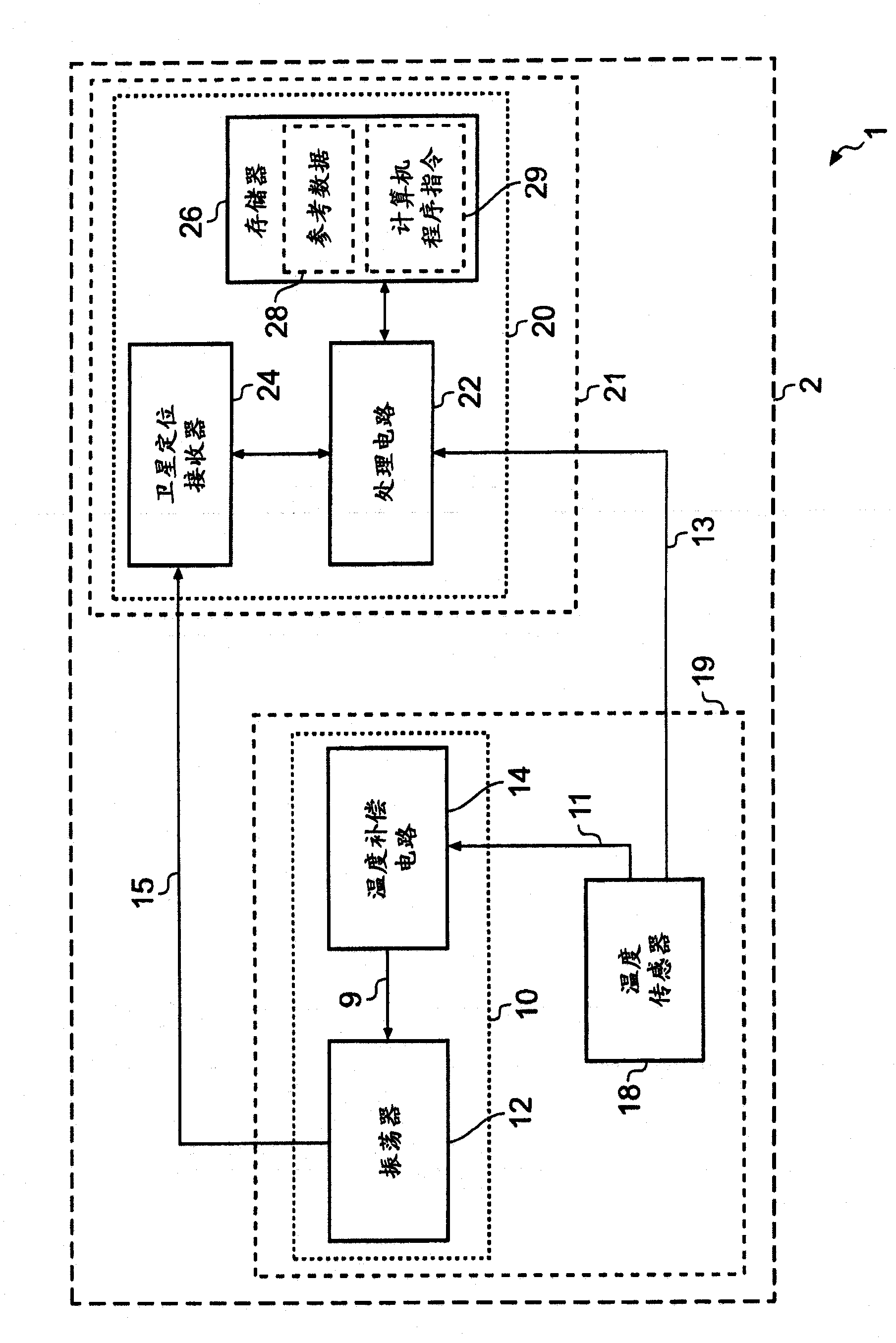
[0026] The drawings show a device 1 comprising: a temperature compensated oscillator 10; a satellite positioning circuit 20; and a temperature sensor 18 configured to provide a first control output 11 to the temperature compensated oscillator 10 and to the satellite positioning circuit 20 provides a second control output 13 .

[0027] figure 1 Device 1 is shown. The device 1 may be an electronic device. For example, figure 1 The device 1 shown in may be part of a hand-held portable electronic device such as a mobile phone, portable music player, personal digital assistant or dedicated satellite navigation device.

[0028] The device 1 comprises a temperature compensated oscillator 10 , a temperature sensor 18 , a satellite positioning circuit 20 and a connection device 2 .

[0029] The connection device 2 is configured to provide an electrical interconnection operatively coupling the temperature compensated oscillator 10 , the temperature sensor 18 and the satellite positi...


PUM


Abstract

An apparatus and a method, the apparatus comprising: a temperature compensated oscillator; satellite positioning circuitry; and a temperature sensor configured to provide a first control output to the temperature compensated oscillator and to provide a second control output to the satellite positioning circuitry.

Description

technical field [0001] Embodiments of the invention relate to timing. In particular, these embodiments relate to timing for receiving satellite positioning signals. Background technique [0002] Satellite positioning receivers receive signals from remote satellites to determine their location. Signals are transmitted by satellites using carrier waves. For example, the signal carrier transmitted by satellites operating in accordance with the Global Positioning System (GPS) has a frequency of 1.575 GHz. [0003] Satellite positioning receivers use oscillators to receive transmitted satellite signals. This oscillator is used to perform a down-conversion from the carrier frequency to the baseband frequency. [0004] Certain factors, such as temperature, can change the oscillation frequency of an oscillator, making it indeterminate. This uncertainty has an impact on the size of the frequency band that a satellite positioning receiver scans when searching for satellite positi...

Claims


Application Information

Patent Timeline
Patent Type & Authority Applications(China)
IPC IPC(8): G01S1/00
CPCG01S19/235
Inventor P·G·伊德
Owner NOKIA CORP
Learn More