Encoding method and encoding device for compression encoding of moving images

A processing method and dynamic image technology, applied in image communication, television, electrical components, etc., can solve the problems of high-speed irrelevance, inability to grasp the number of macroblocks, measure the degree of high-speed processing, etc., achieve low power consumption, The effect of realizing the power consumption effect

Inactive Publication Date: 2011-09-14
PANASONIC CORP
View PDF1 Cites 3 Cited by
  • Summary
  • Abstract
  • Description
  • Claims
  • Application Information

AI Technical Summary

Problems solved by technology

[0007] However, in order to determine whether the difference image is 0, that is, whether the DCT processing and quantization processing can be skipped, it is necessary to actually perform a dynamic search on each macro block (macro block) and then generate the difference image, so it cannot be done before frame processing starts. Grasp the number of macroblocks that can skip DCT processing and quantization processing
Therefore,

Method used


Image

  • Encoding method and encoding device for compression encoding of moving images
  • Encoding method and encoding device for compression encoding of moving images
  • Encoding method and encoding device for compression encoding of moving images

Examples


Embodiment approach 1

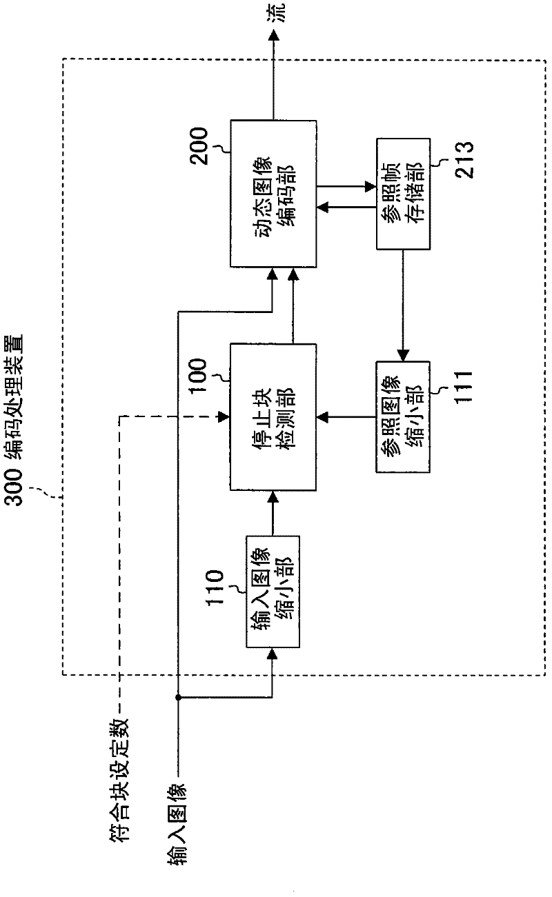
[0062] figure 1 It is a block diagram showing the configuration of the encoding processing device according to Embodiment 1 of the present invention. Such as figure 1 As shown, the encoding processing device 300 is composed of an input image reduction unit 110 , a reference image reduction unit 111 , a stop block detection unit 100 , a video encoding unit 200 , and a reference frame storage unit 213 .

[0063]

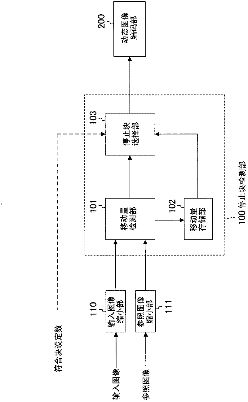
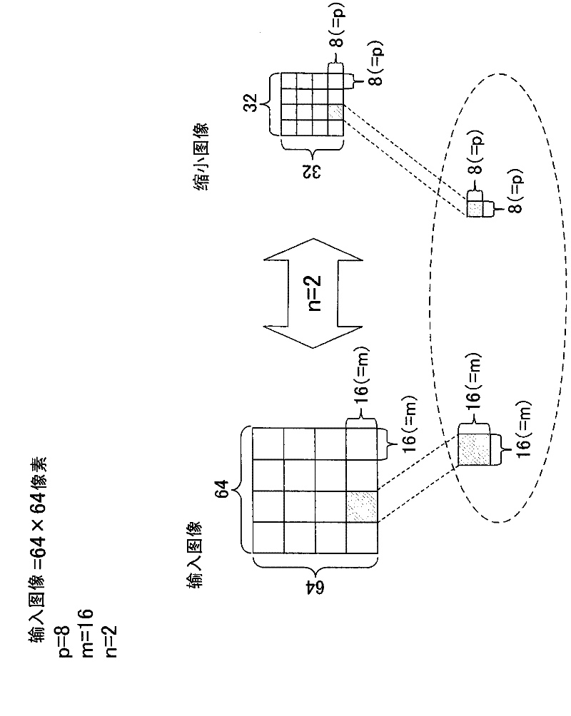
[0064] The input image reduction unit 110 receives an input image to be encoded, reduces the frame image by n times (n is an integer greater than or equal to 1), and outputs the frame image to the stop block detection unit 100 . Similarly, the reference image reduction unit 111 also inputs the reference frame from the reference frame storage unit 213 storing encoded frames (reference frames), reduces the frame image by n times, and outputs it to the stop block detection unit 100. In the stop block detection unit 100, using the input image input from the input image...

Embodiment approach 2

[0096] In Embodiment 2, the implementation content which further developed the content demonstrated in Embodiment 1 is demonstrated.

[0097] In Embodiment 1, a certain increase in speed and power consumption can be achieved by creating a certain number or more of stop blocks per frame. However, if Figure 7 As shown in the example of , when a certain block is continuously designated as a stop block in multiple frames, since it is forcibly coded as "motion vector = 0" and "difference image = 0", in multiple frames always output the same image as the previous frame continuously. There is no problem when the screen is at a standstill without moving even one pixel, but when the amount of movement calculated by Eq. If the image is updated only once (not designated as a moving block), the quality of the moving image may deteriorate. In Embodiment 2, the content of implementation to solve this problem will be described.

[0098] The set number of coincident blocks that defines th...

Embodiment approach 3

[0107] Also in Embodiment 3, implementation details further developed from the contents described in Embodiment 1 will be described.

[0108] In the description of Embodiment 1, the position of the stop block in the coded frame is determined by the stop block detection unit 100 , and the block set as the stop block is skipped when the video coder 200 encodes next. Part of the encoding process.

[0109] However, in the case of this structure, the sequential execution figure 1 The processing in the stop block detection unit 100 and the processing in the moving image encoding unit 200 (refer to Figure 10 ). In Embodiment 3, a method for further speeding up will be described.

[0110] In Embodiment 1, using figure 1 An example is shown in which the stop block detection unit 100 for setting the stop block and the video encoding unit 200 for performing encoding processing are constituted by different units. On the other hand, in the encoding processing device 300b of this embo...


PUM


Abstract

A stop block detection unit (100) is provided in the front stage of a moving image encoding unit (200). The stop block detection unit (100) divides a frame to be processed into multiple blocks and sorts the blocks in the frame in order of increasing movement. The number of blocks designated by "relevant block setting number" input from the outside to an encoding device (300) are set as "stop blocks," starting with the one with the least movement. With respect to the blocks that correspond to stop blocks, the moving image encoding unit (200) executes inter-encoding for the moving image by forcibly setting "movement vector = 0" without performing a movement search, and forcibly substituting "DCT coefficient = 0" without performing DCT and quantification processing.

Description

technical field [0001] The present invention relates to a device having a motion picture function such as a digital camera, a mobile phone with a camera, and a motion image compression coding technique for creating or using image content. Background technique [0002] In recent years, moving picture compression coding technologies such as MPEG (moving picture experts group) that perform high-efficiency coding have been rapidly put into practical use, and are widely used in video cameras, mobile phones, and the like. [0003] In encoding technologies such as MPEG, various encoding modes are defined in standards. For example, in MPEG-4, there are "intra-frame coding mode" and "inter-frame coding mode". In the inter-frame coding mode, an image area that has a strong correlation with the target image is detected from a frame that has been coded (hereinafter referred to as a reference frame) (hereinafter referred to as a dynamic search), and only the image after the dynamic sear...

Claims


Application Information

Patent Timeline
IPC IPC(8): H04N7/32H04N7/30
CPCH04N19/00781H04N19/00145H04N19/00278H04N19/00127H04N7/26132H04N7/26244H04N7/50H04N7/26111H04N19/132H04N19/137H04N19/176H04N19/61
Inventor 田中康晴
Owner PANASONIC CORP
Why Eureka
Try Eureka