Eureka AIR delivers breakthrough ideas for toughest innovation challenges, trusted by R&D personnel around the world.

Injection mould with ejection and linkage mechanisms

A technology of ejection mechanism and linkage mechanism, which is applied in the field of mold design, can solve problems such as high cost, complex oil cylinder structure, and low production efficiency, and achieve the effects of saving processing costs, improving production efficiency, and simple structure

Inactive Publication Date: 2011-09-21
HAIER GRP CORP +1
View PDF3 Cites 4 Cited by
  • Summary
  • Abstract
  • Description
  • Claims
  • Application Information

AI Technical Summary

Problems solved by technology

[0008] The invention provides an injection mold with an ejection linkage mechanism, which can solve the problems that the existing injection mold adopts the oil cylinder ejection mechanism, the oil cylinder structure is complex, the cost is high, and the production efficiency is low.

Method used


Image

  • Injection mould with ejection and linkage mechanisms
  • Injection mould with ejection and linkage mechanisms
  • Injection mould with ejection and linkage mechanisms

Examples


Embodiment 1

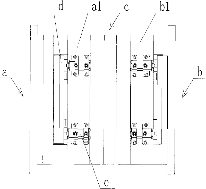
[0039] see figure 1 , an injection mold with an oil cylinder ejection mechanism includes a fixed platen assembly a, a movable platen assembly b, and an intermediate plate assembly c, the fixed platen assembly includes a fixed platen a1, the movable platen assembly includes a movable platen b1, a fixed platen assembly a, and a movable platen assembly b There are ejector plates d on both sides, oil cylinders e are respectively fixed on the fixed platen a1 and movable platen b1, and their heads are connected to the ejector plate d, in order to achieve synchronous ejection of products, a total of 8 oil cylinders e are required on both sides of the multi-layer mold Symmetrically installed, all cylinders e are connected to hydraulic equipment through oil separators; after the mold is opened, the hydraulic equipment drives cylinder e to move, and the head of cylinder e drives the ejector plate to eject the product.

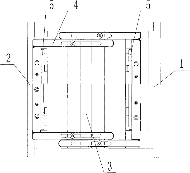
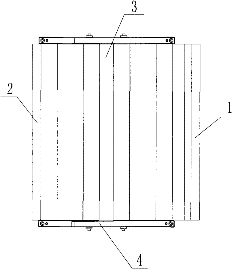
[0040] see Figure 2 to Figure 4 , an injection mold with an eject...

Embodiment 2

[0045] In this embodiment, the ejector mechanism is a limit rod mechanism, which is arranged in the inner cavity of the mold, and includes a limit rod 7 and a limit cavity 8. One end of the limit rod 7 is threaded as a threaded connection part 71, and the other end has a convex The edge-shaped limit blank head 72 and the threaded connection part 71 are screwed and fixedly connected with the ejector plate 5 . When the injection mold of the present invention is a multi-layer injection mold, a limit rod mechanism is also respectively set between the movable template assembly and the intermediate plate assembly, and between the intermediate plate assembly and the fixed template assembly. If the mold opening stroke is small, the two directions The limit pull rod mechanisms on the top can be set relatively. If the mold opening stroke is large, in order to avoid increasing the thickness of the mold, the limit pull rod mechanisms in the two directions should be staggered. Wherein, the...


PUM


Abstract

The invention provides an injection mould with ejection and linkage mechanisms, thus providing a solution to problems of complex oil cylinder structure, high cost and low productivity which exist in present injection moulds employing an oil cylinder ejection mechanism. In the invention, two ejection mechanisms are installed. One end of the ejection mechanisms are connected to liftout plates on the side of the mould core, with the other end connected to one mould side where a cavity is located. The ejection mechanisms are directly driven by mould opening actions of the mould to power the liftout plates so as to eject products. Employing a mechanical structure, the ejection mechanisms of the injection mould are characterized by simple structure, low cost and short injection moulding cycle, and play a key role in achieving fast and efficient manufacturing for the injection mould.

Description

technical field [0001] The invention relates to the field of mold design, in particular to an injection mold with an ejection linkage mechanism. Background technique [0002] Usually, when molded products, the cavity of the single-layer mold is in the fixed mold part, the core is in the movable mold part, and the movable mold part needs to have an ejection action to achieve the purpose of ejecting multiple products. The mold of the multi-layer mold Both fixed and movable molds need to have ejection action to achieve the purpose of ejecting multiple products at the same time. At present, an oil cylinder mechanism is generally used to drive the ejector plate to complete the ejection of the product. The oil cylinder mechanism of the single-layer mold is fixed on the movable platen, and the oil cylinder mechanism of the multi-layer mold is fixed on the fixed and movable platen. The head of the oil cylinder is connected to the ejector plate. , all oil cylinders are connected to ...

Claims


Application Information

Patent Timeline
Patent Type & Authority Applications(China)
IPC IPC(8): B29C45/26B29C45/40
Inventor 赵西金张平王怀国刘红徐丽丽刘军
Owner HAIER GRP CORP
Why Eureka
Eureka Blog
Learn More