Lifting jack hydraulic pressure machine

A jack and press technology, applied in the field of pressure machinery, can solve problems such as damage to the oil cylinder, safety accidents, and the falling of the workpiece to be processed, and achieve the effect of avoiding damage

Active Publication Date: 2011-09-21
CHANGSHU TONGRUN AUTO ACCESSORY
View PDF9 Cites 13 Cited by
  • Summary
  • Abstract
  • Description
  • Claims
  • Application Information

AI Technical Summary

Problems solved by technology

[0005] But the technical scheme that CN101830075A recommends still has the following shortcoming: the one, the operator's labor intensity is big and influences work efficiency, because the workpiece frame needs to be adjusted according to the difference of processed workpiece, so, when wanting to be positioned at the first, the first When the bulky workpiece rack between the two longitudinal arms moves up or down, the operator is very laborious. When the operator is weak, it is often necessary to increase the number of personnel, otherwise it is difficult to move the workpiece rack; the second is as a dive device There is a risk of damage to the oil cylinder, because the cylinder column (also called the piston column) of the oil cylinder is limited in extending to the outside of the cylinder, so if the cylinder column reaches the limit position and continues to work, that is, continue to supply oil to the high-pressure oil chamber, Then there is no doubt that the oil cylinder will be damaged, and even cause safety accidents; the third is that there are hidden dangers to personal safety during the processing of the processed workpiece, because in the operation process, there will inevitably be a force between the cylinder of the cylinder column and the processed workpiece The position deviation between the two parts will cause the workpiece to be processed to fall or pop up and attack the operator

Method used


Image

  • Lifting jack hydraulic pressure machine
  • Lifting jack hydraulic pressure machine
  • Lifting jack hydraulic pressure machine

Examples


Embodiment Construction

[0025] In order to enable the examiners of the patent office, especially the public, to understand the technical essence and beneficial effects of the present invention more clearly, the applicant will describe in detail the following in the form of examples, but none of the descriptions to the examples is an explanation of the solutions of the present invention. Any equivalent transformation made according to the concept of the present invention which is merely formal but not substantive shall be regarded as the scope of the technical solution of the present invention.

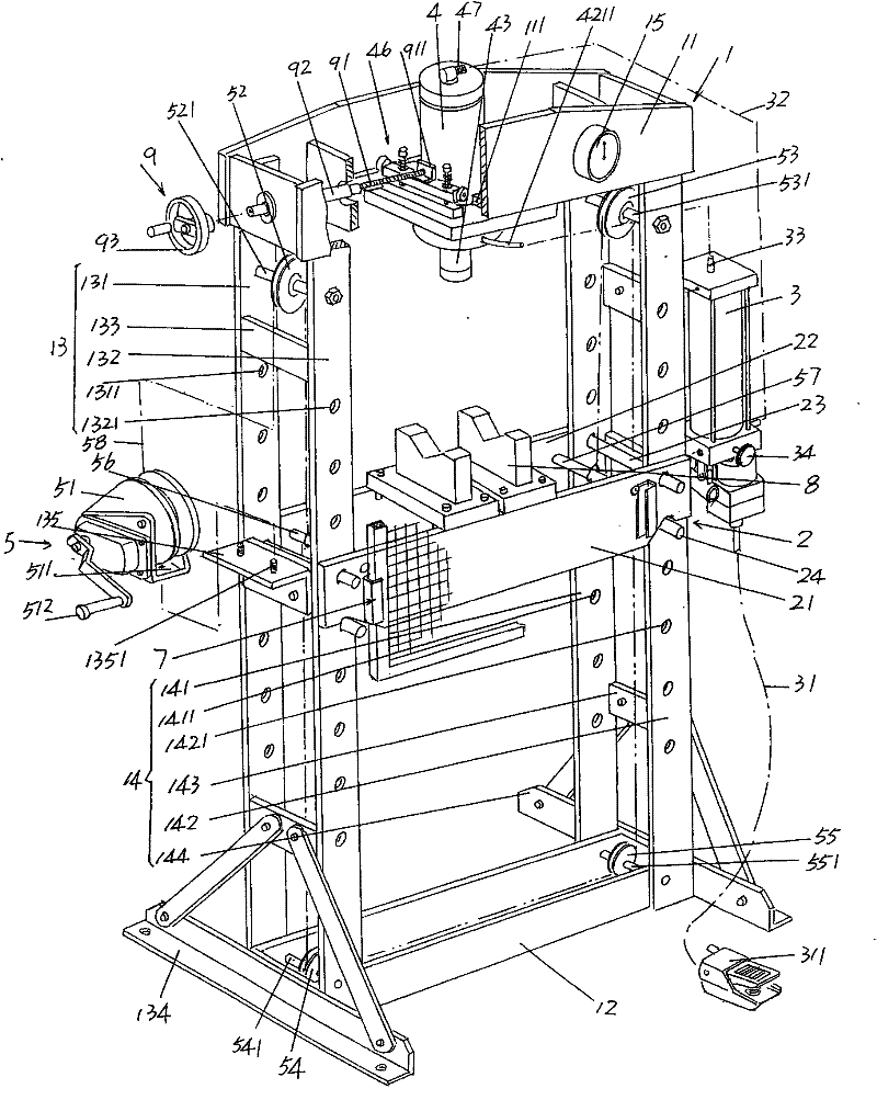
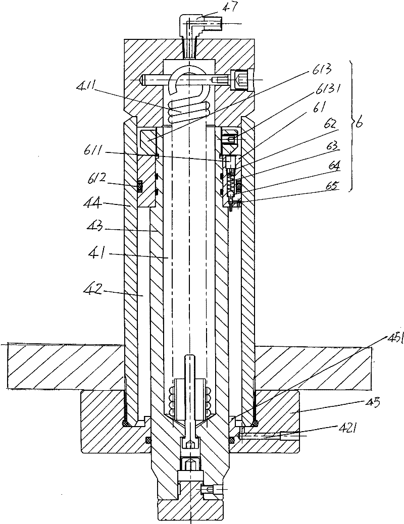
[0026] Please see figure 1 and figure 2 ,exist figure 1 The frame 1 with the same structure as that of CN101830075A mentioned by the applicant in the background technology column is given in , the frame 1 is composed of upper and lower beams 11, 12 and first and second longitudinal arms 13, 14, the upper beam 11 is a (hollow-out) rectangular structure that is closed around and penetrates up and down. A gui...


PUM


Abstract

The invention discloses a lifting jack hydraulic pressure machine, which belongs to the technical field of pressure machines. The machine comprises an upper cross beam, a lower cross beam, a machine frame, work piece frames, a lifting jack body and an oil cylinder, wherein the machine frame is connected between the upper cross beam and the lower cross beam and consists of a first longitudinal arm and a second longitudinal arm which are longitudinally parallel to each other; the work piece frames are arranged on the first longitudinal arm and the second longitudinal arm in an up-and-down movement mode and are positioned between the upper cross beam and the low cross beam; the lifting jack body is arranged on the outer side of the first longitudinal arm or the outer side of the second longitudinal arm; and the oil cylinder is arranged on the upper cross beam and is connected with a hydraulic oil circuit of the lifting jack body. The machine is characterized by also comprising a work piece frame lifting mechanism, wherein the work piece frame lifting mechanism is used for lifting and lowering the work piece frames, arranged on the machine frame and connected with the work piece frames. The machine has the advantages that: the operation intensity of operators can be obviously reduced, and the operation efficiency can be obviously improved; the oil cylinder can be prevented from being damaged; and the condition that the operators are hurt because a machined workpiece is ejected out accidentally can be prevented, so that operation safety is reflected.

Description

technical field [0001] The invention belongs to the technical field of pressure machinery, and in particular relates to a jack hydraulic press. Background technique [0002] As is well known in the industry, compared with the dedicated large and medium-sized hydraulic presses, jack hydraulic presses can play a role in supplementing gaps. The specific performances are strong adaptability, small size, simple operation and low investment. Production lines, construction sites waiting for work, repair sites in the electromechanical maintenance industry, vehicles such as maintenance departments of various vehicles, and can be applied to homes, etc. [0003] Jack hydraulic presses have been reported in documents, especially Chinese patent documents, such as utility model authorization announcement number CN201205566Y (jack hydraulic press), another example CN2144571Y (manual hydraulic press), and another example CN201385455Y (hand screw with additional jack type layer press), etc....

Claims


Application Information

Patent Timeline
Patent Type & Authority Applications(China)
IPC IPC(8): B30B1/32B30B15/00B30B15/28
Inventor 石永良唐洁刘羽毕昇
Owner CHANGSHU TONGRUN AUTO ACCESSORY
Why Eureka
Try Eureka