Motorcycle projector headlight

A technology for motorcycles and headlights, which is applied in the direction of headlights, vehicle lighting systems, motor vehicles, etc., and can solve problems such as cost increase

Active Publication Date: 2011-09-21
STANLEY ELECTRIC CO LTD
View PDF7 Cites 14 Cited by
  • Summary
  • Abstract
  • Description
  • Claims
  • Application Information

AI Technical Summary

Problems solved by technology

[0010] However, in the projection type headlamp 200 for motorcycles with the above-mentioned structure, although it is possible to cover the darkened region when the vehicle body is tilted (the upper edge of the low beam light distribution pattern P1 formed obliquely with the horizontal line H-H when the vehicle body is tilted) The enclosed triangular area A, refer to Figure 17 (b)) Illumination is performed. However, in addition to the lamp 210 for the low beam beam, two turning lamps 220 are added to the structure, so there is a problem that the cost increases accordingly.
[0011] In addition, in the projection type headlamp 200 having the above-mentioned structure, in order to form the overhead light distribution pattern for illuminating signs and the like, an additional dedicated optical system has to be added, which further increases the cost.

Method used


Image

  • Motorcycle projector headlight
  • Motorcycle projector headlight
  • Motorcycle projector headlight

Examples


Embodiment Construction

[0057] Hereinafter, a motorcycle projection headlamp according to an embodiment of the present invention will be described with reference to the drawings.

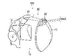
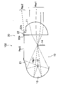
[0058] Such as figure 1 , figure 2 As shown, the motorcycle projection headlamp 100 according to this embodiment has the main light distribution optical system 10 and the additional optical system 20 .

[0059] [Optical system 10 for main light distribution]

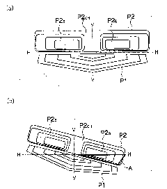
[0060] The optical system 10 for main light distribution is an optical system configured to irradiate and form a light distribution pattern P1 for low beam beam (refer to image 3 (a)) light, and if figure 1 , figure 2 As shown, it has the following parts like a general projection headlight: a projection lens 11; a light source 12 (for example, a halogen bulb, a HID bulb); Near the light source 12, the second focal point is set near the upper edge of the lampshade 14; In addition, in figure 1 For convenience of illustration, the lampshade 14 is omitted. ...


PUM


Abstract

A motorcycle projector headlight, comprises: a first reflector; a second reflector located adjacent to the outer side of an opening of the first reflector so as to make the light towards the outer side of the opening of the first reflector from the light emitted from a light source income into the second reflector; a diffusion lens arranged along the radiation direction of the reflection light from the second reflector and composed of a light incoming surface on which the reflection light from the second reflector incomes; an emitting surface for making the reflection light from the second reflector which incomes into the lens from the light incoming surface be emitted as a diffusion light diffusing along the vertical and horizontal directions, wherein the emitting surface is configured to be a concave curved surface, the horizontal cross section of the concave curved surface comprises an elliptical arc being bilateral symmetray relative to the long axis or short axis and bending towards the light incoming surface side and the vertical cross section of the concave curved surface comprises an arc and an elliptical arc bending towards one side on the horizontal surface passing through the center of the circle or ellipse and the light incoming surface side in the circle or ellipse.

Description

technical field [0001] The present invention relates to a projection type headlamp for motorcycles, in particular to a projection type headlamp for motorcycles capable of forming a bank light distribution pattern and an overhead light distribution pattern, wherein the bank light distribution The pattern is used to illuminate areas that become dark when the vehicle body is tilted, and the overhead light distribution pattern is used to illuminate signs and the like. Background technique [0002] In the past, in the field of headlights for motorcycles, there have been proposed projection type headlights configured as follows: Figure 17 (a)) When the tilt occurs, prevent the main light distribution pattern P1 from tilting due to the low beam beam etc. (refer to Figure 17 (b)) resulting in a triangular area A (refer to Figure 17 (b)) It is darkened, and the triangular area A is illuminated when the vehicle body is tilted (for example, Patent Document 1). [0003] Such as Fig...

Claims


Application Information

Patent Timeline
Patent Type & Authority Applications(China)
IPC IPC(8): F21S8/10F21V13/04F21V7/09F21V5/00F21W101/10F21W101/027F21W107/17
CPCF21S48/1258F21S48/1159F21W2101/10F21Y2101/02F21S48/1382F21Y2115/10F21S41/255F21S41/338F21W2102/18
Inventor 芥川贵志江原徹坂元忠史阿部忠信长谷川纯一
Owner STANLEY ELECTRIC CO LTD
Why Eureka
Try Eureka