
Drive module and electronic apparatus

A technology of driving modules and driven bodies, which is applied in the direction of TV, electrical components, TV system components, etc., can solve the problems of inconsistency and defocusing, etc., with little possibility of achieving, suppressing the decline of manufacturing efficiency, and reducing the cost of defective products Effect

Inactive Publication Date: 2011-09-21
SEIKO INSTR INC
View PDF3 Cites 2 Cited by
  • Summary
  • Abstract
  • Description
  • Claims
  • Application Information

AI Technical Summary

Problems solved by technology

[0005] In the above driving module, if the optical axis K' of the lens frame 200 (lens unit) is obliquely arranged with respect to the axis M' of the module frame 201 and the module lower plate 204 ( Figure 12 Indicated by the symbol 200' in the image), there may be problems such as so-called defocusing in which the focus of one side of the captured image is inconsistent

Method used


Image

  • Drive module and electronic apparatus
  • Drive module and electronic apparatus
  • Drive module and electronic apparatus

Examples


Embodiment Construction

[0046] (drive module)

[0047] Hereinafter, an embodiment of the drive module of the present invention will be described based on the drawings. In this embodiment, the driving module of the imaging lens unit of the camera is taken as an example for description. In addition, as an example of the actuator for driving the lens unit, a case where a shape-memory alloy wire is used will be described as an example. In addition, in each of the following figures, the axial direction of the lens unit may be referred to as the Z direction, and the radial direction may be referred to as the R direction.

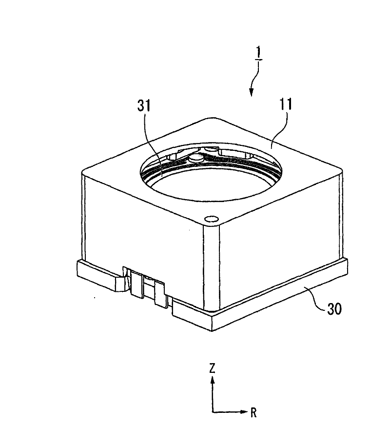
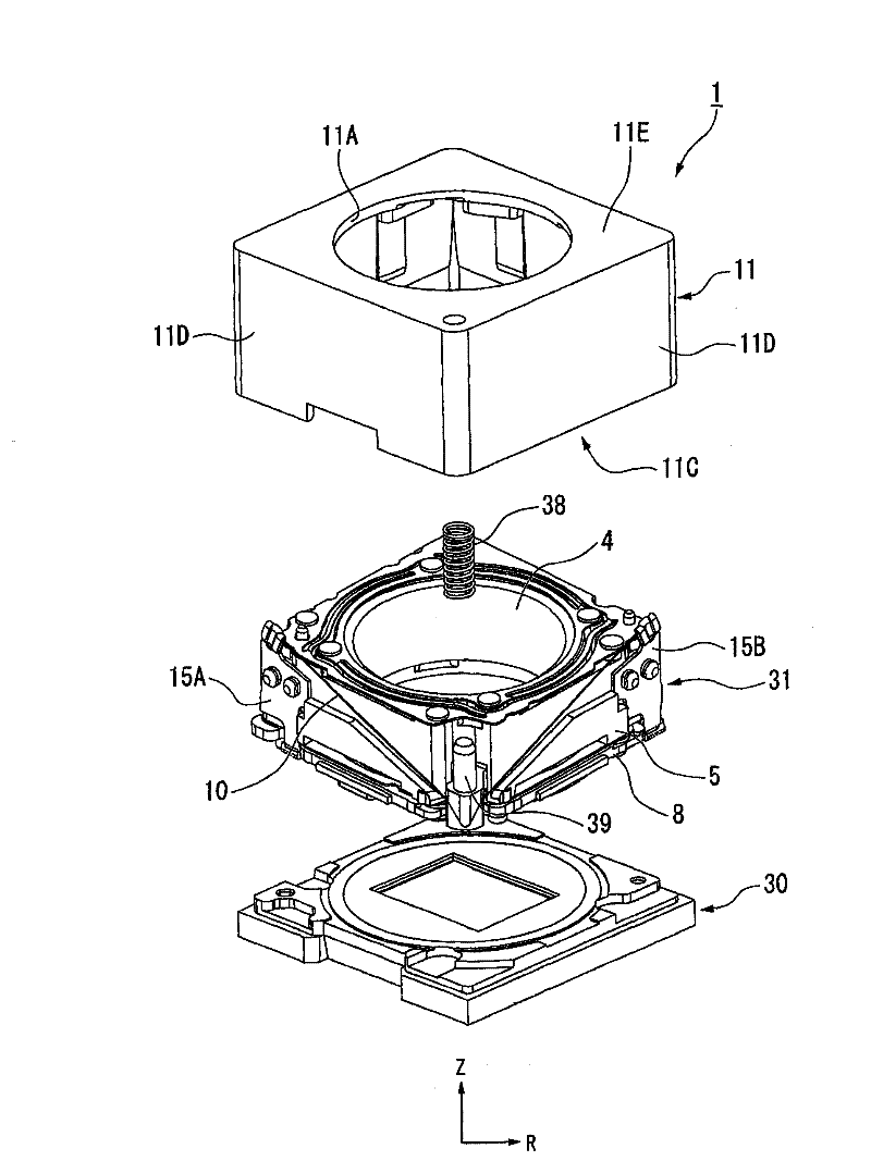
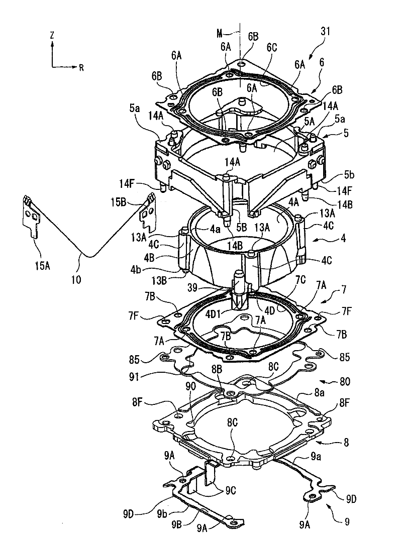
[0048] figure 1 It is an external perspective view of the drive module 1 . figure 2 It is an exploded perspective view showing a schematic structure of the drive module 1 . Such as figure 1 with figure 2 As shown, the drive module 1 of the present embodiment is configured in a box shape as a whole.

[0049] After the drive module 1 is assembled, it is fixed on a substrate that...


PUM


Abstract

A drive module and an electronic apparatus which can detect inclination of a driven member with high degree of accuracy are provided. A module lower panel and an intermediate member are formed with a plurality of notched portions which expose the inner peripheral portion of a lower leaf spring when viewing a drive unit from below.

Description

technical field [0001] The present invention relates to a drive module and an electronic device suitable for driving, for example, an optical system to adjust a focus position, or used as an actuator for driving a movable member. Background technique [0002] Conventionally, there have been proposals for various drive modules that utilize expansion and contraction of shape memory alloy wires to drive for autofocus and focus adjustment in small electronic devices such as camera-equipped mobile phones. [0003] Figure 12 is an explanatory diagram of an existing drive module, and is equivalent to Figure 4 A cross-sectional view of a portion of the B-B line. [0004] Such as Figure 12 As shown, the existing drive module has: a cylindrical lens frame (driven body) 200, holding the lens unit (not shown in the figure); a cylindrical module frame (support body) 201, housing the lens frame 200 inside and the lower plate spring 202, which is connected to the end faces of the lens...

Claims


Application Information

Patent Timeline
Patent Type & Authority Applications(China)
IPC IPC(8): G02B7/04G03B13/34G01B11/26
CPCG03B3/10G03B5/00G02B7/08G02B13/001G03B13/36G02B7/28H04N23/00
Inventor 野边哲也小棚木进
Owner SEIKO INSTR INC
Learn More