Electric part connection mechanism in operating machine

A technology of electrical components and connecting mechanisms, applied to electrical components, components of connecting devices, connections, etc., can solve problems such as bad conditions, terminal bending, poor installation operability, etc., and achieve the effect of reducing the number of man-hours

Active Publication Date: 2011-09-21
HONDA MOTOR CO LTD
View PDF9 Cites 4 Cited by
  • Summary
  • Abstract
  • Description
  • Claims
  • Application Information

AI Technical Summary

Problems solved by technology

[0006] in will Figure 8 In the case where the shown harness connector 90 is connected to the side of the voltage changeover switch 70 for a large current, since there is no guide for insertion on the side of the voltage changeover switch 70 for a large current, a plurality of male terminals 72 are exposed. , Therefore, there are problems such as terminal bending during mating, and poor mounting workability due to insertion and withdrawal loads, etc.
[0007] On the other hand, due to the use environment of the generator, water sometimes enters the back side of the movable switch 71 from the gap between the square window 81 of the operation panel 80 and the movable switch 71.
The water then enters the inside of the switch part 70 from the movable part of the movable switch 71, flows out from the drain port 73, and is guided to the side of the power generation part circuit along the part of the cable 74 arranged on the back side. bad situation
[0008] In addition, the structures described in each of the above-mentioned patent documents are for connecting a plurality of terminals formed in a junction box and an aggregated connector, and do not disclose a structure for connecting a relay connector between terminal groups.
[0009] In addition, none of the patent documents describes the structure related to preventing water from entering the connection part of the terminal group.

Method used


Image

  • Electric part connection mechanism in operating machine
  • Electric part connection mechanism in operating machine
  • Electric part connection mechanism in operating machine

Examples


Embodiment Construction

[0033] Below, refer to Figure 1 ~ Figure 7A as well as Figure 7B An example of an embodiment of the electrical component connection mechanism in the working machine of the present invention will be described.

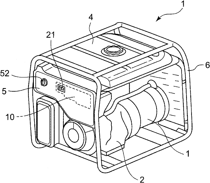
[0034] Apply the electrical component connection mechanism in the working machine of the present invention to figure 1 The internal combustion generator (working machine) 1 is shown. The internal combustion generator 1 is constructed by mounting the following components on the bracket 6: an engine 2 driven by gasoline fuel; an alternator 3 driven by the engine 2 to generate electricity; a fuel tank 4 for storing gasoline fuel; And a control panel (operation panel) 5 for performing various operations and the like.

[0035] The control panel 5 is equipped with the following components: an engine switch 51 for driving the engine; a voltage switching switch 21 for switching the output voltage (100V and 200V); various display units (not shown) for displaying operating ...


PUM


Abstract

Provided is a connection mechanism which connects a switch portion 20 of a generator 1 to an assembling terminal 11 of a junction box 10 having plural female terminals 12 connected to a generator circuit 13 via a relay connector 30, wherein the relay connector 30 forms a defining wall 31 inside a cylindrical body so that a fitting portion 32 is provided at one side of the defining wall 31 so as to be fitted to the switch portion 20, and plural relay terminals are attached to the other side so as to be connected to the plural female terminals 12, and wherein holes 35 are provided in the defining wall so as to respectively face the front ends of the relay terminals 33. Accordingly, the switch portion 20 and the assembling terminal 11 are integrally and directly connected to each other via the relay connector 30.

Description

technical field [0001] The present invention relates to a connection mechanism for connecting electric parts such as a switch part and a junction box having a circuit of a power generation part, the electric parts such as a switch part being attached to an operation panel of a working machine such as a generator driven by an engine In the above, the power generation part circuit is configured to have a plurality of terminals, and the present invention particularly relates to an electrical component connection mechanism in a work machine with a relay connector that connects the electrical component (switch part) and the wiring The box is connected as one. Background technique [0002] As an electrical component mounted on the operation panel of an engine-driven generator, there are such Figure 8 A voltage switch 70 is shown for high current use. The voltage selector switch 70 for high current is configured to be fixed on the back side (Xiang side) of the operation panel 80,...

Claims


Application Information

Patent Timeline
Patent Type & Authority Applications(China)
IPC IPC(8): H01R13/02H01R13/46H01R13/52
CPCH01R13/5219H01R2107/00H01H23/14H01R31/06
Inventor 山本刚义中田泰弘
Owner HONDA MOTOR CO LTD
Why Eureka
Try Eureka