Power conversion apparatus
A technology of power conversion device and main circuit, which is applied in the direction of output power conversion device, structural components of conversion equipment, fixed capacitor shell/package, etc., can solve problems such as heat generation, and achieve the effect of shortening the connection distance
- Summary
- Abstract
- Description
- Claims
- Application Information
AI Technical Summary
Problems solved by technology
Method used
Image

Examples
Embodiment 1
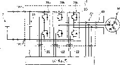
[0025] First, use figure 1 The circuit configuration of the power conversion device of the first embodiment will be described. figure 1 It is a diagram showing the circuit configuration of the power conversion device of the first embodiment.
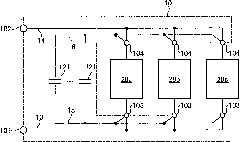
[0026] figure 1 The illustrated power conversion device 1 includes an inverter unit 20 that converts a DC voltage input from a DC power supply 2 to first connection units 101 and 102 serving as input terminals into a three-phase AC voltage, and converts The three-phase AC voltage is output to the three-phase motor M from output terminals provided on the output terminal block 40 . In addition, the first connection part 101 is connected to the negative side of the DC power supply 2 , and the first connection part 102 is connected to the positive side of the DC power supply 2 .
[0027] The inverter section 20 is a switching circuit having switching element sections 20a to 20c having a pair of semiconductor switches connected in series. ...
Embodiment 2
[0062] Next, the power conversion device of Embodiment 2 will be described. The power conversion device of the second embodiment differs from the power conversion device 1 of the first embodiment only in the structure of the main circuit capacitor. Therefore, in the following, refer to Figure 5A ~ Figure 5C The main circuit capacitor of the power conversion device of the second embodiment will be specifically described.
[0063] Figure 5A It is an exploded perspective view of the main circuit capacitor 10a of the second embodiment, Figure 5B is a perspective explanatory view showing the inside of the case 17 of the main circuit capacitor 10a, Figure 5C Yes Figure 5B B-B line profile.
[0064] like Figure 5A As shown, in the main circuit capacitor 10a of the second embodiment, the first wiring member 14a on the positive side, the second wiring member 16a on the positive side, the capacitive element part 12a, the second wiring member 15a on the negative side, and the...
Embodiment 3
[0073] Next, the power conversion device of the third embodiment will be described. The power conversion device of the third embodiment is different from the image 3 The power conversion device 1 shown has the same structure.
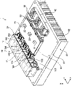
[0074] Image 6 It is a perspective view showing the appearance of the power conversion device 1b of the third embodiment. like Image 6 As shown, in the power conversion device 1 b , an input terminal block 71 and a connection terminal block 73 are arranged on the upper surface of the base 51 . The input terminal block 71 is provided adjacent to the output terminal block 40 , and the connection terminal block 73 is arranged at a position facing the first connection portions 101 , 102 protruding from the main circuit capacitor 10 .
[0075] In addition, in the power conversion device 1b, a pair of conductive wiring members 72, 72 are spanned between the input terminal block 71 and the connection terminal block 73, and each end portion of the wiring...
PUM
 Abstract
Description
Claims
Application Information
 - R&D
- Intellectual Property
- Life Sciences
- Materials
- Tech Scout
- Unparalleled Data Quality
- Higher Quality Content
- 60% Fewer Hallucinations
Browse by: Latest US Patents, China's latest patents, Technical Efficacy Thesaurus, Application Domain, Technology Topic, Popular Technical Reports.
© 2025 PatSnap. All rights reserved.Legal|Privacy policy|Modern Slavery Act Transparency Statement|Sitemap|About US| Contact US: help@patsnap.com