Head/slider supporting structure having lead wire inclined relative to slider pad

a support structure and slider technology, applied in the direction of maintaining head carrier alignment, magnetic recording, printed circuit aspects, etc., can solve the problems of static electricity generated in the course of adhesion discharged to break the slider or the head, and the head is not easy to maintain the alignment of the head carrier, etc., to achieve excellent connection performance and excellent connection performance

Inactive Publication Date: 2008-08-26
HITACHI GLOBAL STORAGE TECH NETHERLANDS BV
View PDF7 Cites 5 Cited by
  • Summary
  • Abstract
  • Description
  • Claims
  • Application Information

AI Technical Summary

Benefits of technology

[0009]During the course of studying the measures for the inferior connections, we found that an effective method for carrying out the adequate solder ball connection is, in addition to an improvement of solder wetting properties of the pad or improvement of material of solder, to shorten a connection distance 23 between the slider pad 13 and the lead pad 29. The connection distance 23 is a shortest distance between the extreme end portion of the lead pad 29 and the end of the slider pad 13. To shorten the connection distance 23, there is a method for moving the lead wire 21 closer to the slider 11 to thereby narrow the space 25 and shorten the horizontal distance, which however has a limit in terms of securing a positional tolerance when the slider 11 is fixed to the dielectric layer 17a.
[0013]It is therefore a feature of the present invention to provide a head / slider supporting structure provided, in a solder ball connection of a slider pad and a lead pad, with an excellent connection performance. A further feature of the present invention is to provide a rotating disk storage device having head / slider supporting structure with excellent connection performance.
[0014]In a head / slider supporting structure for solder ball connecting a slider and a lead wire, according to a feature of the invention, a connection distance between an end of a slider pad and an extreme end portion of a lead wire is shortened to thereby enhance the performance of solder connection.
[0018]The dielectric layer laminated on the platform of the metallic layer provided forwardly of the slider pad extends toward the slider pad beyond the end of the platform whereby it is possible to prevent the conductor layer from short-circuiting with the metallic layer in the solder ball connection. Further, the conductor layer extends toward the slider pad beyond the end of the dielectric layer whereby the dielectric layer can be prevented from burning when a laser beam is irradiated.
[0020]In the second aspect, the lead wire is inclined in a direction different from that of the first aspect with respect to the slider pad to thereby shorten the connection distance. The crossing angle may be any angle over 90 degrees, preferably, in the range of about 100 to 120 degrees.
[0023]According to the present invention, it is possible to provide a head / slider supporting structure having connection performance excellent in a solder ball connection of a slider pad and a lead pad. Further, according to the present invention it is possible to provide a rotating disk storage device provided with the head / slider supporting structure excellent in connection performance.

Problems solved by technology

Recently, as recording density enhances, demand of the head with respect to the control characteristics becomes severe, influence of weight, arrangement and the like of the lead wire on positional control of the head cannot be ignored.
Further, in the supersonic adhesion method, there is a fear that static electricity generated in the course of adhesion is discharged to break the slider or the head, and there is pointed out limitation as the adhesion method for further miniaturized head / slider.

Method used


Image

  • Head/slider supporting structure having lead wire inclined relative to slider pad
  • Head/slider supporting structure having lead wire inclined relative to slider pad
  • Head/slider supporting structure having lead wire inclined relative to slider pad

Examples


Embodiment Construction

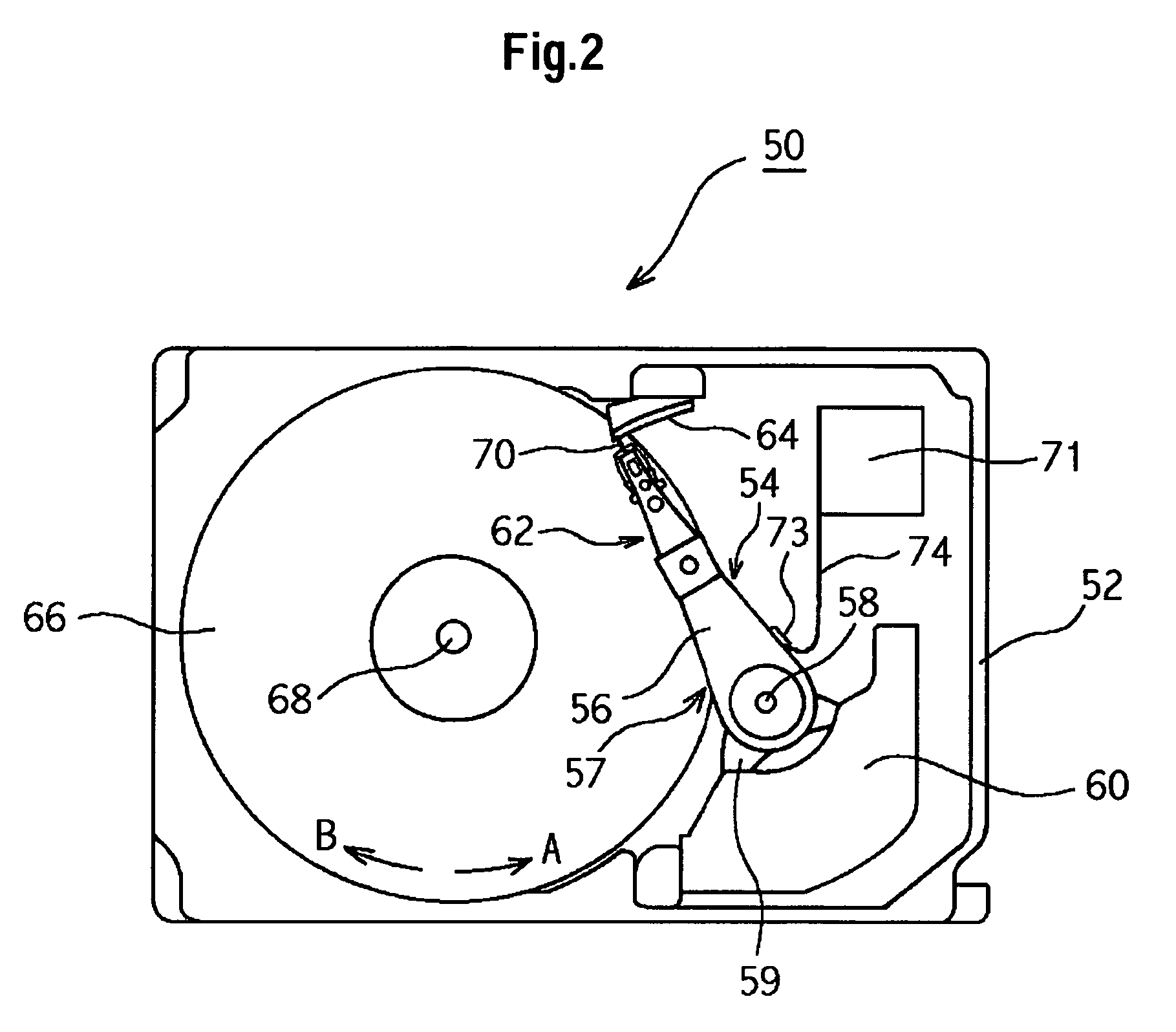
[0033]In the following, the embodiments of the present invention will be described with reference to the drawings. The same reference numerals denote the same structural elements throughout the drawings. FIG. 2 is a plan view showing the schematic structure of a magnetic disk drive 50 applied to the embodiments of the present invention. A base 52 forms a closed space together with a cover (not shown), and encases therein an actuator head suspension assembly 54, a magnetic disk 66, a ramp 64, and a semiconductor element 71 and the like.

[0034]The magnetic disk 66 is fixed to a spindle hub (not shown) so as to be rotated about a spindle shaft 68 by a spindle motor (not shown) provided below, and it has a magnetic layer formed at least on one surface thereof. Two magnetic disks 66 or more may also be stacked. With respect to the direction in which the magnetic disk 66 is rotated, the arrow A is called positive rotation and the arrow B is called reverse rotation in relation to the actuat...


PUM

PropertyMeasurementUnit
crossing angleaaaaaaaaaa
angleaaaaaaaaaa

Abstract

Embodiments of the invention provide a head / slider supporting structure which has connection properties excellent in solder ball connections of a slider pad and a lead pad. According to one embodiment, in a head / slider supporting structure for connecting a slider and a lead wire by re-flowing a solder ball, a connection distance between a slider pad and an extreme end portion of the lead wire is reduced to enhance the performance of solder connection. The lead wire is inclined forwardly of the slider pad.

Description

CROSS-REFERENCES TO RELATED APPLICATIONS[0001]This application claims priority from Japanese Patent Application No. JP2004-058021, filed Mar. 2, 2004, the entire disclosure of which is incorporated herein by reference.BACKGROUND OF THE INVENTION[0002]The present invention relates to the technique for solder-connecting a head provided on a slider of a magnetic disk drive, a magneto-optical disk drive or the like and a lead wire connected to a circuit base plate, and more specifically, to the technique for enhancing the positive properties of connection between a slider pad and a lead wire using a solder ball.[0003]In the magnetic disk drive, a head for converting a magnetic signal to an electric signal carries out writing or reading of data with respect to the magnetic disk. A head and a slider constitute a head / slider, and a supporting structure called a suspension assembly supports the head / slider. The head / slider flies, in reading or writing data, above the magnetic disk which rot...

Claims


Application Information

Patent Timeline
Patent Type & Authority Patents(United States)
IPC IPC(8): G11B5/60G11B5/48G11B21/21H05K1/18H05K3/32H05K3/34H05K3/40
CPCG11B5/484G11B5/4853H05K3/3442H05K1/189H05K3/326H01L2224/742H05K2201/0397H05K2201/09063H05K2201/10727H05K2203/041H05K3/4092Y02P70/50
Inventor TSUCHIDA, HIROYASUTSUCHIYA, TATSUMIMUROKAWA, TAKAAKIMATSUMOTO, YUHSUKEUEMATSU, YOSHIOTANAKA, TATSUYA
Owner HITACHI GLOBAL STORAGE TECH NETHERLANDS BV
Why Eureka
Try Eureka