Fuel injection system and cylinder head with a central fuel reservoir

a fuel injection system and cylinder head technology, applied in liquid fuel feeders, machines/engines, mechanical equipment, etc., can solve the problems of fuel reservoir, and limited maximum height of pressure level, and achieve the effect of simple production and simple installation

Inactive Publication Date: 2005-08-04
ROBERT BOSCH GMBH
View PDF9 Cites 5 Cited by
  • Summary
  • Abstract
  • Description
  • Claims
  • Application Information

AI Technical Summary

Benefits of technology

[0009] In a further advantageous feature of the invention, the fuel reservoir is embodied as a cylindrical, elongated bore in the cylinder head. By drilling, the shape and position of the fuel reservoir can be produced with precision, and it can be disposed as close as possible to the respective receiving bores for the injectors by way of which the fuel is injected into the combustion chambers. As an alternative to this, the fuel reservoir is formed by an insert part in the operation of casting the cylinder head. This makes production extremely simple and requires no additional machining steps.
[0010]

Problems solved by technology

A disadvantage of this fuel injection system is that the fuel reservoir, which is disposed on the outside of and in the vicinity of the respective cylinder of the cylinder head, requires additional space in th

Method used


Image

  • Fuel injection system and cylinder head with a central fuel reservoir
  • Fuel injection system and cylinder head with a central fuel reservoir

Examples


first embodiment

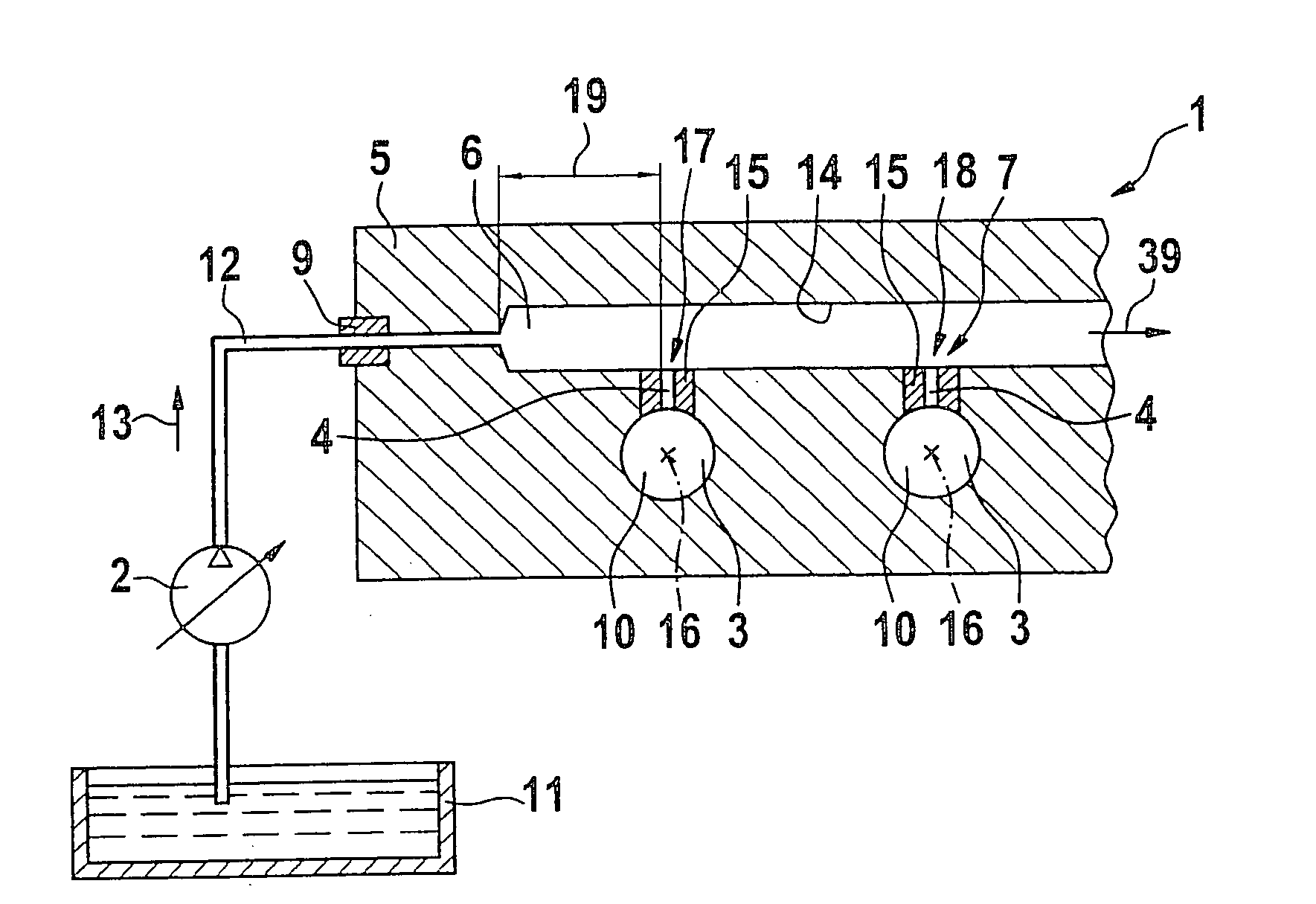
[0016] In FIG. 1, a fuel injection system according to the invention is shown schematically, having a fuel reservoir integrated, in the form of a recess, into a cylinder head. In self-igniting internal combustion engines, the fuel reservoir is embodied as a high-pressure reservoir (common rail); in direct-injection gasoline engines, the fuel reservoir is designed for a lower pressure level. The fuel injection system proposed according to the invention can be used both in self-igniting internal combustion engines and in direct-injection gasoline engines.

[0017] Fuel is pumped from a fuel tank 11 by a feed pump 2 and is furnished in compressed form in a central fuel reservoir 1, which in self-igniting internal combustion engines is designed as a high-pressure reservoir, and from there is delivered to the combustion chambers 38 of the engine. The feed pumped by the feed pump 2 passes via a sealing body 9 to reach the high-pressure fuel reservoir 1, which according to the invention is em...

second embodiment

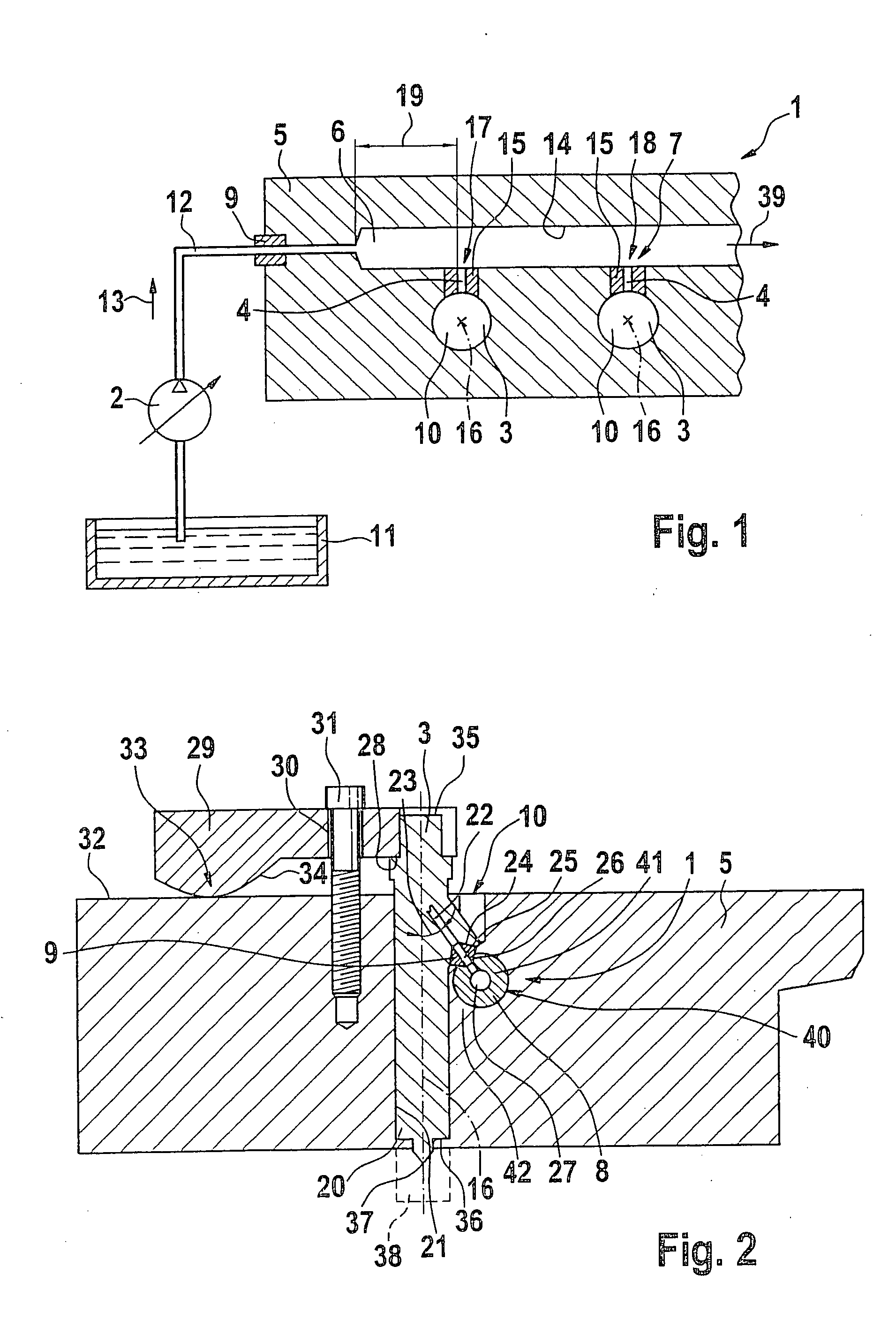
[0022] In FIG. 2, the invention is shown in a sectional view, with a fuel reservoir which extends along the injectors disposed in the cylinder head and is integrated into the cylinder head.

[0023] The high-pressure delivery of fuel to the fuel injectors in this variant embodiment of the invention includes a fuel reservoir 1, which is formed by a cylindrical tube 8 that, in the vicinity of the fuel injectors 3, is let into a recess 6 or 40, of suitable size, in the cylinder head 5 of the self-igniting internal combustion engine. The fuel reservoir 1 formed by the cylindrical tube 8 communicates directly, via sealing bodies 9, with the various fuel injectors 3, so that separate connecting conduits or lines are not needed.

[0024] The injector 3 shown as an example in FIG. 2 is inserted into the cylinder head 5 in a fastening opening 10.

[0025] As can be seen from the further exemplary embodiment of the invention, shown in section in FIG. 2, the fuel injector 3 is introduced into the fas...


PUM


Abstract

A fuel injection system for an internal combustion engine and to a cylinder head for such a fuel injection system, in which a central fuel reservoir is provided between a feed pump and a plurality of injectors to be supplied with fuel, which each communicate with the central fuel reservoir via respective high-pressure lines, and the injectors are mounted in a cylinder head of the engine for injecting fuel into a plurality of combustion chambers, and the fuel reservoir and/or the high-pressure lines are at least partly integrated into the cylinder head of the engine.

Description

FIELD OF THE INVENTION [0001] For supplying fuel to combustion chambers, for instance in direct-injection internal combustion engines, injection systems are used that have a central pressure reservoir (common rail), by way of which highly compressed fuel is delivered to the various injectors of the engine. In such engines, the highest possible injection pressure is generally advantageous, since that makes higher engine power levels and reduced emissions possible. BACKGROUND OF THE INVENTION [0002] In currently known injection systems for supplying fuel to internal combustion engines, it is known to embody a central pressure reservoir in the form of a tube which communicates with the various injectors of the engine via high-pressure lines and is supplied with fuel form the fuel tank via a feed pump. A tube serving for instance as a high-pressure reservoir is known to be disposed parallel to and along a cylinder head of a self-igniting internal combustion engine. The tube walls enclos...

Claims


Application Information

Patent Timeline
IPC IPC(8): F02F1/24F02B3/06F02M37/00F02M55/00F02M55/02
CPCF02B3/06F02M55/005F02M55/02F02M55/025F02M61/14F02F1/24F02M55/00
Inventor BRAEUER, CHRISTIANHOLL, STEFAN
Owner ROBERT BOSCH GMBH
Why Eureka
Try Eureka