

Carrier sensing method and circuit as well as microcontroller
A carrier sensing and circuit technology, applied in line transmission monitoring/testing, electrical components, distribution line transmission systems, etc., can solve problems such as low carrier energy, complex software algorithms, and low meter reading signals, and achieve low hardware costs , Expand the application environment, and the effect of simple software algorithm
Active Publication Date: 2011-09-21
QINGDAO EASTSOFT COMM TECH +1
View PDF6 Cites 2 Cited by
- Summary
- Abstract
- Description
- Claims
- Application Information
AI Technical Summary
Problems solved by technology
This solution requires complex software algorithms and a lot of hardware costs, which increases product costs; and with the substantial increase in the number of nodes in the network, the waiting time is very long
In addition, because the attenuation of the power line communication is very large, and the energy of the input carrier signal cannot be set at the same time, it is not suitable for the carrier with small energy. In the application of power line carrier meter reading, the voltage of the meter reading signal is usually low, so the carrier energy Also low, it is difficult to achieve accurate carrier sensing through existing methods
Method used
View moreImage
Smart ImageViewing Examples

Examples
Embodiment Construction
Login to View More PUM
 Abstract
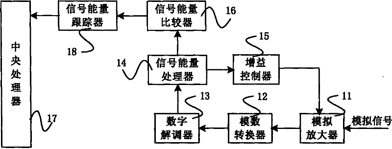
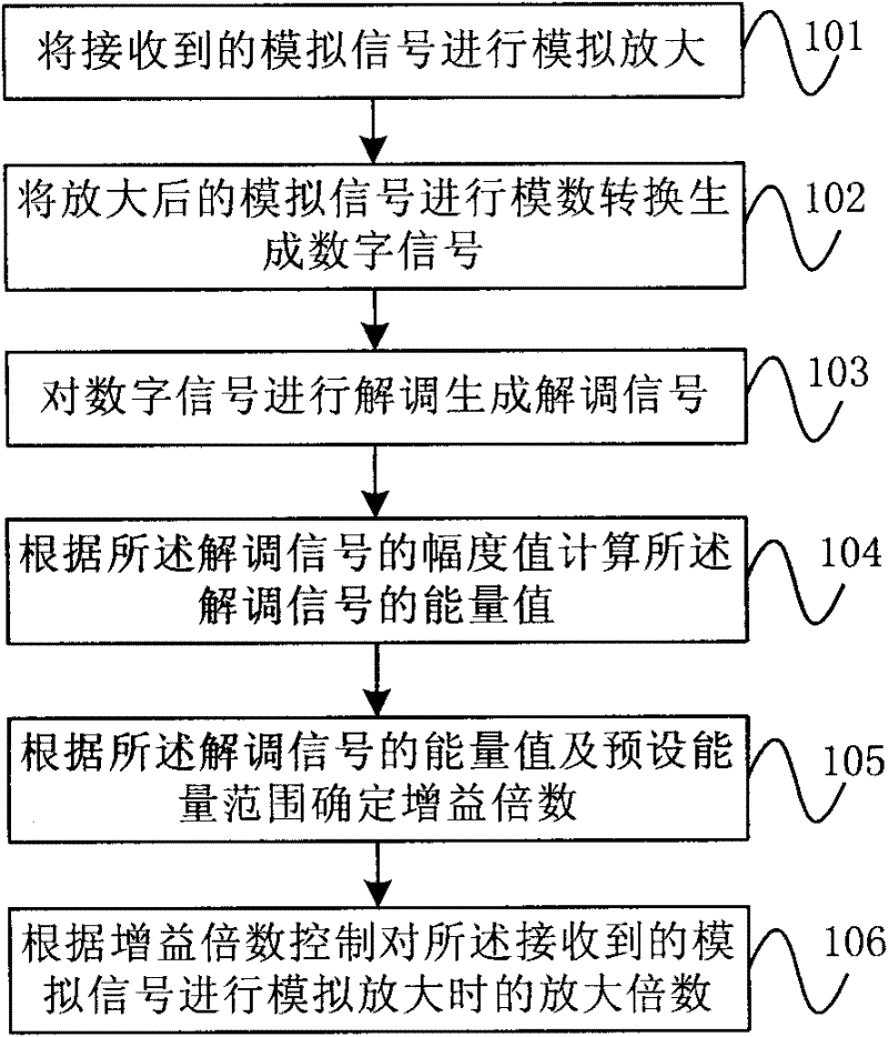
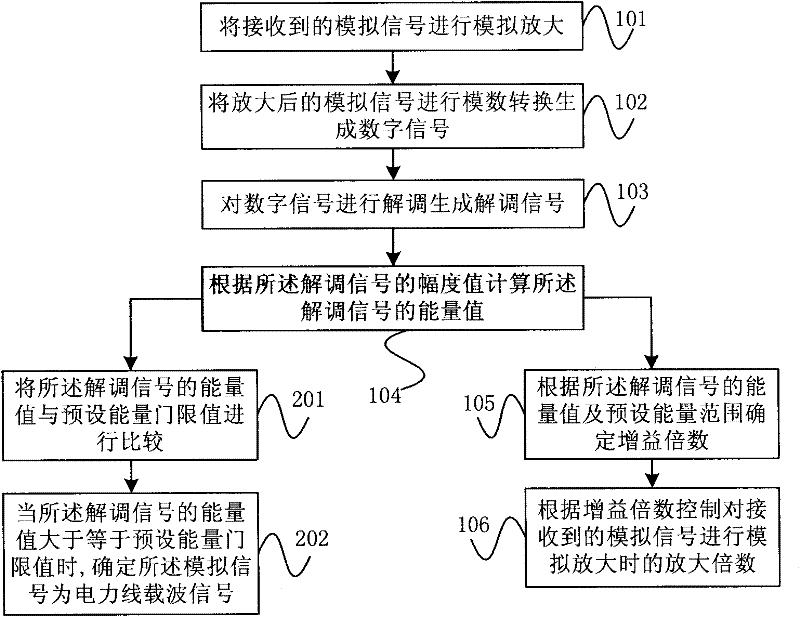
The invention provides a carrier sensing method and circuit as well as a microcontroller. The carrier sensing method comprises the following steps: carrying out analog amplification on a received analog signal; carrying out analog-to-digital (A / D) conversion on the amplified analog signal to generate a digital signal; demodulating the digital signal to generate a demodulated signal; calculating an energy value of the demodulated signal according to an amplitude value of the demodulated signal; determining a gain multiplication factor according to the energy value and a preset energy range of the demodulated signal; and controlling an amplification factor in the case of analog amplification on the received analog signal according to the gain multiplication factor. By utilizing the carrier sensing method and circuit as well as the microcontroller, the power line carrier signal with smaller energy can be sensed, thus expanding application environments.
Description
Carrier Sense Method, Circuit and Microcontroller technical field The embodiments of the present invention relate to the field of power line communication, in particular to a carrier sensing method, circuit and microcontroller in power line communication. Background technique The Carrier Sense Multiple Access (CSMA for short) technology in power line communication senses the carrier to avoid possible conflicts and collisions of signals transmitted between nodes. An existing CSMA implementation scheme listens to the channel before a certain node sends a signal. If the channel is idle, the node generates a random delay time according to the prediction of the current network load. When the random delay time ends, the channel if is still idle, the node sends the packet. This solution requires complex software algorithms and a large amount of hardware costs, which increases the cost of the product; and with the substantial increase in the number of nodes in the network, the w...
Claims
Login to View More Application Information
Patent Timeline
 IPC IPC(8): H04B3/46H04B3/54
CPCH04L12/413
Inventor崔健潘松胡亚军谷志坤王锐
OwnerQINGDAO EASTSOFT COMM TECH