

Video data processing device
A technology for video data and processing devices, applied in the field of video data processing devices, can solve the problems of no image display on the display, intermittent display, long time consumption, etc.
- Summary
- Abstract
- Description
- Claims
- Application Information
AI Technical Summary
Problems solved by technology
Method used
Image

Examples
no. 1 Embodiment approach
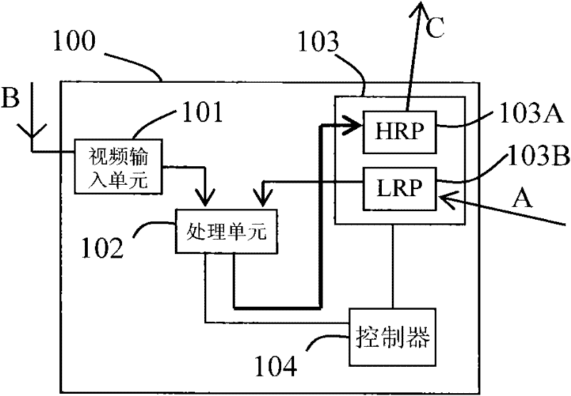
[0042] image 3 It is a diagram showing the configuration of the video data processing device 100 according to the first embodiment. Such as image 3 As shown, the video data processing device 100 includes: a video input unit 101 , a processing unit 102 , a transmission unit 103 and a controller 104 . The transmission unit 103 has a high-speed path unit (HRP) 103A and a low-speed path unit (LRP) 103B, and these two units can perform data transmission independently of each other. Moreover, the low-speed channel unit 103B is connected to the processing unit 102 .
[0043] Next, the processing flow of the video data processing device 100 according to the first embodiment will be described.
[0044] First, the first coded video data B is received from the video input section 101 of the video data processing device 100 . In addition, the low-speed channel unit 103B of the transmission unit 103 is used as an input channel, and the second coded video data A is received from an ex...
no. 2 Embodiment approach
[0049] Figure 4 It is a diagram showing the configuration of the video data processing device 200 according to the second embodiment. The video data processing device 200 according to the second embodiment is the same as the video data processing device 100 according to the first embodiment except that a selection section 202 and a decoding section 203 are provided instead of the processing section 102 .
[0050] that is, image 3 As shown, the video data processing device 200 includes: a video input unit 201 , a selection unit 202 , a decoding unit 203 , a transmission unit 204 and a controller 205 . The transmission unit 204 has a high-speed path unit (HRP) 204A and a low-speed path unit (LRP) 204B, and the two units can perform data transmission independently of each other. Furthermore, the low-speed channel unit 204B of the transmission unit 204 is connected to the selection unit 202 .
[0051] Next, the processing flow of the video data processing device 200 according...
no. 3 Embodiment approach
[0057] Figure 5 It is a diagram showing the configuration of the video data processing device 300 according to the third embodiment. Video data processing device 300 according to the third embodiment is the same as video data processing device 100 according to the first embodiment except that decoding units 302A and 302B and selecting unit 303 are provided instead of processing unit 102 .
[0058] that is, Figure 5 As shown, the video data processing device 300 includes: a video input unit 301 , decoding units 302A, 302B, a selection unit 303 , a transmission unit 304 and a controller 305 . The transmission unit 304 has a high-speed path unit (HRP) 304A and a low-speed path unit (LRP) 304B, and the two units can perform data transmission independently of each other. In addition, the low-speed path unit 304B of the transmission unit 304 is connected to the decoding unit 302B.
[0059] Next, the processing flow of the video data processing device 300 according to the third ...
PUM
 Abstract
Description
Claims
Application Information