
Rectangular secondary battery and method of manufacturing the same

a secondary battery and rectangular technology, applied in the field ofrectangular secondary batteries, can solve the problems of difficult to increase the volumetric energy density of secondary batteries, and achieve the effect of high volumetric energy density and high reliability

Active Publication Date: 2021-02-02
SANYO ELECTRIC CO LTD
View PDF7 Cites 0 Cited by
  • Summary
  • Abstract
  • Description
  • Claims
  • Application Information

AI Technical Summary

Benefits of technology

This design enhances volumetric energy density and reliability by optimizing internal space and incorporating a fuse and insulator system to prevent reconnection and displacement, while also providing a short-circuit mechanism for safety against overcharging.

Problems solved by technology

For this reason, it is difficult to increase the volumetric energy density of the secondary battery.

Method used


Image

  • Rectangular secondary battery and method of manufacturing the same
  • Rectangular secondary battery and method of manufacturing the same
  • Rectangular secondary battery and method of manufacturing the same

Examples


first modification

[0080]A rectangular secondary battery according to a first modification differs from the rectangular secondary battery 20 according to the embodiment in the shape of the inner insulator. FIG. 12 illustrates a surface of a sealing plate facing an electrode body and the electrode body of the rectangular secondary battery according to the first modification, after the electrode body has been attached. An inner insulator 112 includes an insulator base portion 112a disposed along the sealing plate 2; and an insulator first side wall 112b and an insulator second side wall 112c, which are formed at ends of the insulator base portion 112a in the longitudinal direction of the sealing plate 2. An inner insulator 114 includes an insulator base portion 114a disposed along the sealing plate 2; and an insulator first side wall 114b and an insulator second side wall 114c, which are formed at ends of the insulator base portion 114a in the longitudinal direction of the sealing plate 2.

[0081]As illus...

second modification

[0086]A rectangular secondary battery according to a second modification differs from the rectangular secondary battery according to the first modification in the shape of the inner insulator. FIG. 16 illustrates a surface of the sealing plate 2, facing the electrode boy, of the rectangular secondary battery according to the second modification after components have been attached. On the surface of the sealing plate 2 facing inside of the battery, the flange portion 7a of the positive electrode terminal 7 and the positive-electrode current collector 6 are disposed via an inner insulator 212. On the surface of the sealing plate 2 facing inside of the battery, the flange portion 10a of the negative electrode terminal 10 and the negative-electrode current collector 9 are disposed via an inner insulator 214.

[0087]The inner insulator 212 includes an insulator base portion 212a disposed along the sealing plate 2, an insulator first side wall 212b protruding from the insulator base portion...


PUM

PropertyMeasurementUnit
thicknessaaaaaaaaaa
thicknessaaaaaaaaaa
pressureaaaaaaaaaa

Abstract

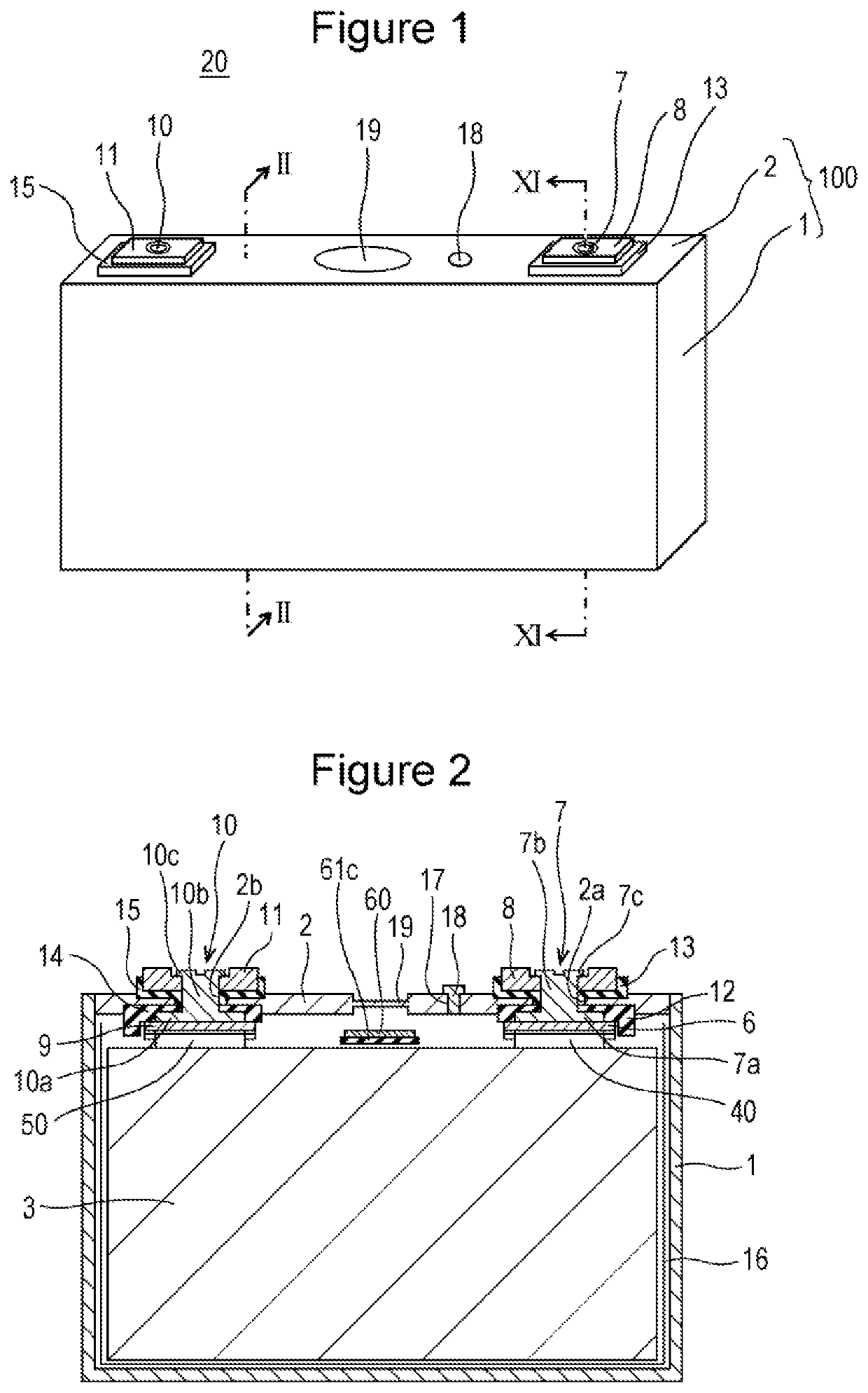
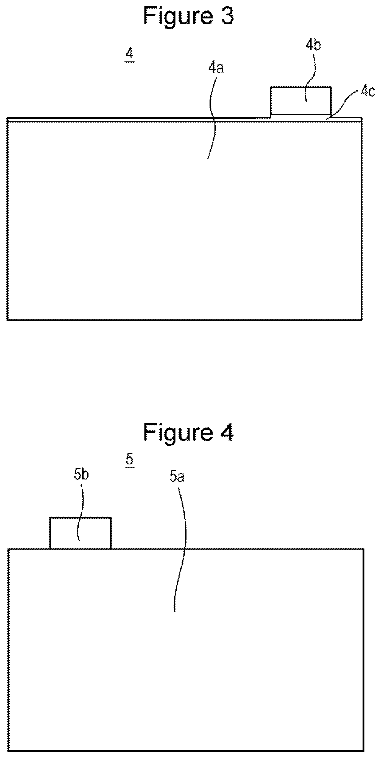
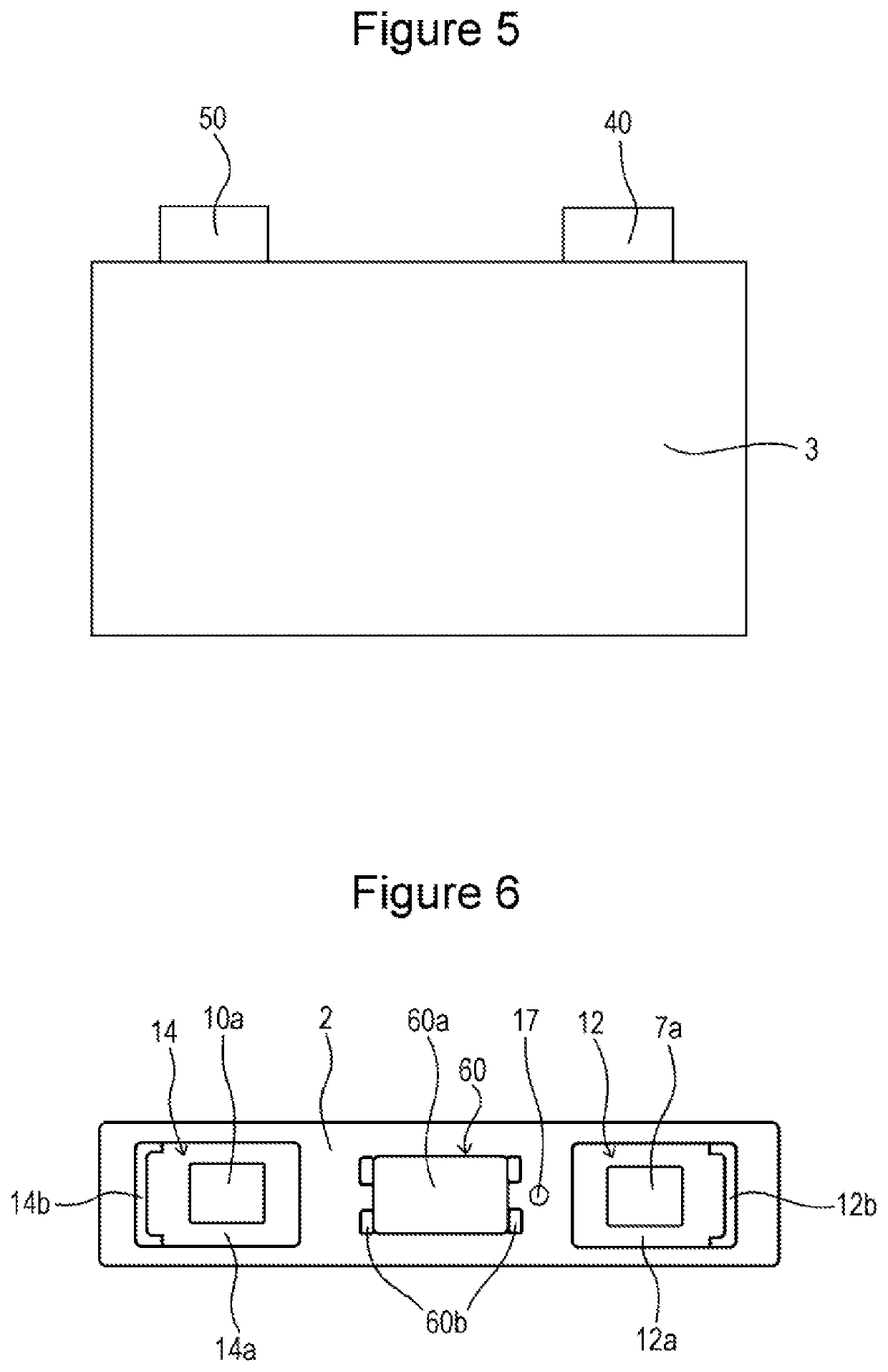
An electrode body, which includes a positive electrode plate and a negative electrode plate, includes a positive-electrode tab group that is composed of a plurality of positive electrode tabs. The positive-electrode tab group is disposed between a sealing plate and an electrode body, and a positive-electrode current collector includes a base portion and a tab connection portion that is folded from an end of the base portion. The base portion of the positive-electrode current collector is connected to a positive electrode terminal, and the tab connection portion of the positive-electrode current collector is connected to the positive-electrode tab group. A fuse portion is formed in the positive-electrode current collector, and a first-insulator second region of a first insulator, which is connected to an inner insulator, is disposed between the base portion and the tab connection portion.

Description

CROSS REFERENCE TO RELATED APPLICATIONS[0001]The present invention application claims priority to Japanese Patent Application No. 2017-126877 filed in the Japan Patent Office on Jun. 29, 2017, the entire contents of which are incorporated herein by reference.BACKGROUND OF THE INVENTIONField of the Invention[0002]The present invention relates to a rectangular secondary battery and a method of manufacturing a rectangular secondary battery.Description of Related Art[0003]Rectangular secondary batteries, such as alkaline secondary batteries and non-aqueous electrolyte secondary batteries, are used as driving electric power sources of electric vehicles (EV), hybrid electric vehicles (HEV, PHEV), and the like.[0004]The rectangular secondary batteries each have a battery case that is composed of a rectangular casing, which has an opening and a bottomed-rectangular-tubular shape, and a sealing plate that seals the opening. The battery case contains an electrode body together with an electro...

Claims


Application Information

Patent Timeline
Patent Type & Authority Patents(United States)
IPC IPC(8): H01M10/0585H01M2/26H01M4/70H01M2/08H01M2/18H01M2/30H01M2/34H01M10/04H01M4/525H01M4/505H01M4/583H01M4/02H01M50/188H01M50/193H01M50/463H01M50/534H01M50/536H01M50/55H01M50/562H01M50/566
CPCH01M10/0585H01M2/08H01M2/18H01M2/26H01M2/30H01M2/348H01M4/70H01M10/0413H01M4/505H01M4/525H01M4/583H01M2004/027H01M2004/028H01M2200/103H01M2200/20H01M2220/20H01M10/0525H01M10/058H01M50/463H01M50/193H01M50/562H01M50/536H01M50/566H01M50/188H01M50/534H01M50/55Y02E60/10H01M50/581Y02P70/50
Inventor WAKIMOTO, RYOICHITAKABAYASHI, HIROSHI
Owner SANYO ELECTRIC CO LTD
Learn More