Surface acoustic wave atomizer
A surface elastic wave and atomization device technology, which is applied in spraying devices, liquid spraying devices, climate sustainability, etc., to achieve stable and efficient atomization and avoid short circuits
- Summary
- Abstract
- Description
- Claims
- Application Information
AI Technical Summary
Problems solved by technology
Method used
Image

Examples
no. 1 approach
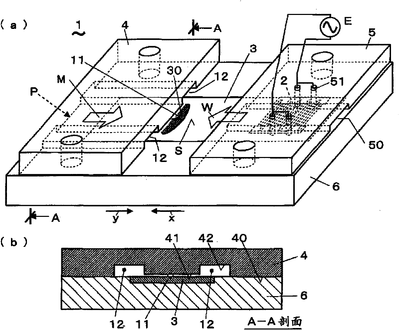
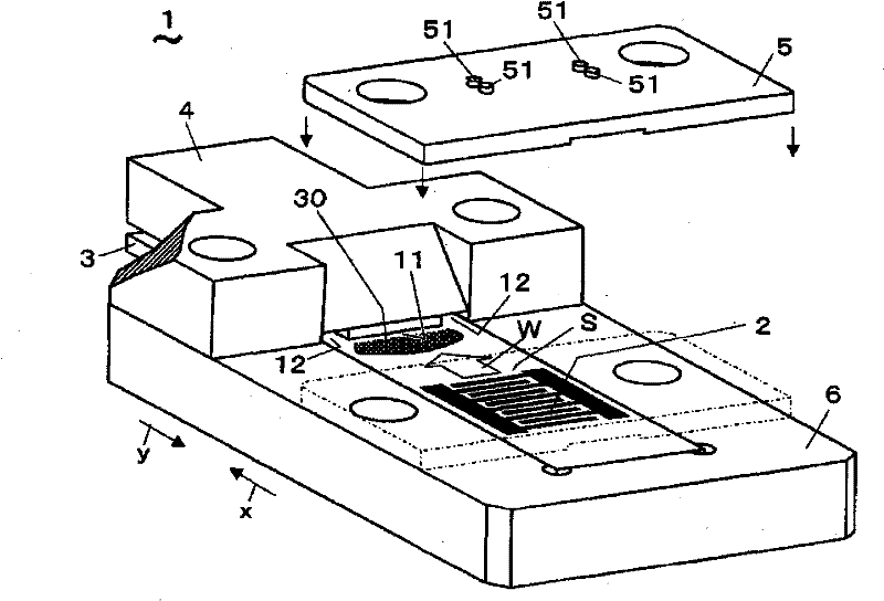
[0031] Hereinafter, a surface acoustic wave atomization device according to an embodiment of the present invention will be described with reference to the drawings. figure 1 (a), (b), figure 2 The surface acoustic wave atomization device according to the first embodiment is shown. The surface acoustic wave atomization device 1 is provided with: a piezoelectric substrate 3, which has a pattern electrode 2 on a surface S that excites a surface acoustic wave W by applying a high-frequency voltage; The atomizing area 30 on the S supplies the liquid M; the contact fixture 5 has an electrode column 51 for applying a voltage to the pattern electrode 2, and is assembled on the piezoelectric substrate 3 from above the pattern electrode 2; the support plate 6, which It is a base member that supports the piezoelectric substrate 3 from below, and the surface acoustic wave atomization device 1 atomizes the liquid M supplied to the surface S of the piezoelectric substrate 3 by the liquid ...
no. 2 approach
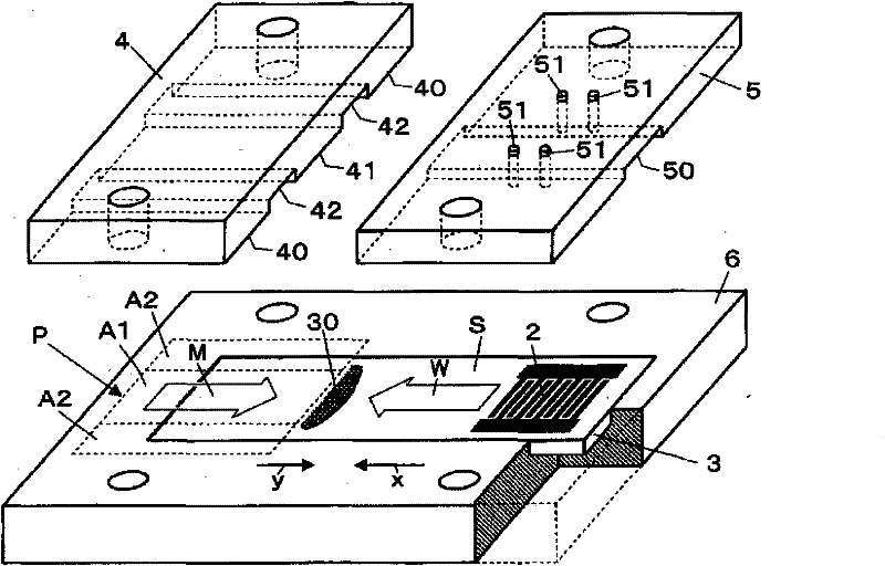
[0043] combine Figure 4 A surface acoustic wave atomization device according to a second embodiment will be described. Compared with the first embodiment, the surface acoustic wave atomization device 1 of the present embodiment differs in the method of forming the micro-slits 11 , but is the same in other respects. That is, instead of forming the inner surface of the lower surface 40 , the surface 41 of the lower surface 40 of the liquid supply member 4 in the region sandwiched by the two grooves 42 is formed with irregularities obtained by roughening the lower surface 40 . The surface 41 formed with unevenness due to such roughening is in contact with the surface S of the piezoelectric substrate 3 , thereby exerting the same effect as that of the above-described micro slits 11 .
[0044] The minute slit 11 in the above-mentioned first embodiment is as fine as about 0.1 to 0.3 μm, and therefore may be affected by machining accuracy and mounting errors. In addition, it was f...
no. 3 approach
[0047] Figure 5 , Figure 6 The surface acoustic wave atomization device according to the third embodiment is shown. Compared with the first and second embodiments, the surface acoustic wave atomization device 1 of this embodiment is different in the position where the micro slit 11 is formed on the piezoelectric substrate 3 , but is the same in other respects. That is, the minute slit 11 is formed in a region on the surface of the piezoelectric substrate 3 where the surface acoustic wave W is not excited. The central region 31 along the longitudinal direction of the piezoelectric substrate 3 is a region where the surface acoustic wave W propagates, and the surface acoustic wave W does not exist in regions on both sides of the region 31 . A region A1 that retains and induces the liquid M is formed in a region on one side where the surface acoustic wave W does not exist. In addition, a protruding portion facing the center line of the piezoelectric substrate 3 is formed at t...
PUM
 Abstract
Description
Claims
Application Information
 - R&D
- Intellectual Property
- Life Sciences
- Materials
- Tech Scout
- Unparalleled Data Quality
- Higher Quality Content
- 60% Fewer Hallucinations
Browse by: Latest US Patents, China's latest patents, Technical Efficacy Thesaurus, Application Domain, Technology Topic, Popular Technical Reports.
© 2025 PatSnap. All rights reserved.Legal|Privacy policy|Modern Slavery Act Transparency Statement|Sitemap|About US| Contact US: help@patsnap.com