Jigger

A jigging machine and jigging technology, applied in the field of jigging machines, can solve the problems of complex structure, inability to adjust speed, poor craftsmanship, etc., and achieve the effects of novel and reasonable structure, prolonging working life and high working efficiency

Inactive Publication Date: 2011-09-28
李国中
View PDF6 Cites 0 Cited by
  • Summary
  • Abstract
  • Description
  • Claims
  • Application Information

AI Technical Summary

Problems solved by technology

[0002] At present, the jigging machine used in the coal preparation industry has a complex structure of the cover plate damper used to control the medium pulse. It needs to overcome the back pressure of the cover plate when the air is sucked in, which is easy to cause cylinder collision, frequent damage to the cylinder, and increased maintenance. , poor reliability
[0003] The lower body of the jig machine adopts a four-edge platform structure directly connected to the upper body, resulting in poor rigidity of the lower body, and frequent cracking of the lower body, which affects production. Difference
[0004] Discharging device: because the speed cannot be adjusted or the general electronic speed is adjusted, it cannot well meet the requirements of the jig sorting process; and the power consumption is large

Method used


Image

  • Jigger
  • Jigger
  • Jigger

Examples


Embodiment Construction

[0022] Below in conjunction with accompanying drawing, the present invention is described in further detail:

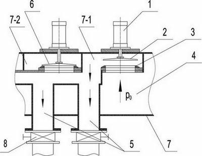
[0023] figure 1 Shown, the present invention comprises valve body 7, and valve body 7 comprises bellows 4, air inlet chamber 7-1, exhaust chamber 7-2 and inlet and outlet pipe 5, and inlet chamber 7-1 communicates with inlet and outlet pipe 5. An air inlet is provided between the air box 4 and the air intake chamber 7-1, and an air outlet is provided between the air intake chamber 7-1 and the exhaust chamber 7-2. 7-1 communicated or isolated intake cover 2, the exhaust port is provided with an exhaust cover 6 that can communicate or isolate the intake chamber 7-1 with the exhaust chamber 7-2, the intake cover 2 and The exhaust cover plate 6 is respectively connected to the piston rod of the sliding cylinder 1, and the cylinder body of the sliding cylinder 1 is fixed on the outer wall of the valve body 7.

[0024] In the above structure, the bellows 4 is isolated fro...


PUM


Abstract

The invention relates to a jigger, in particular to an under-sieve jigger with air chambers in the coal preparation industry. The jigger comprises an upper machine body, a lower machine body and a discharging device, wherein, air inlet and outlet channels of a jigging chamber in the upper machine body are connected with a jigger air valve with cover plates. The jigger is characterized in that the jigger air valve with the cover plates comprises a valve body which consists of an air box, an air inlet chamber, an air exhaust chamber and air inlet and exhaust pipes, wherein the air inlet chamber is communicate with the air inlet and exhaust pipes; an air inlet is arranged between the air box and the air inlet chamber, and an air outlet is arranged between the air inlet chamber and the air exhaust chamber; the air inlet is equipped with an air inlet cover plate, and the air outlet is equipped with an air outlet cover plate; the air inlet cover plate and the air outlet cover plate are respectively connected with piston rods of sliding cylinders; and the sliding cylinder bodies are fixed on the outer wall of the valve body. The adopted air valve with cover plates can replace a cylinder-barrel sliding valve, a butterfly valve and a common valve with cover plates which are used in the market currently; and the air valve has the advantages of air flow, air leakage or cylinder bump, no back pressure from the cover plates in the case of opening the valve, automatic opening function by virtue of positive chamber pressure; in addition, the weight of the machine bodies and energy consumption can be reduced by means of improvement of the lower machine body and the discharging mechanism.

Description

technical field [0001] The invention relates to a jig machine, in particular to an under-screen air chamber jig machine in the coal preparation industry. Background technique [0002] At present, the jigging machine used in the coal preparation industry has a complex structure of the cover plate damper used to control the medium pulse. It needs to overcome the back pressure of the cover plate when the air is sucked in, which is easy to cause cylinder collision, frequent damage to the cylinder, and increased maintenance. , poor reliability. [0003] The lower body of the jig machine adopts a four-edge platform structure directly connected to the upper body, resulting in poor rigidity of the lower body, and frequent cracking of the lower body, which affects production. Difference. [0004] Discharging device: because the speed cannot be adjusted or the general electronic speed is adjusted, it cannot well meet the requirements of the jig sorting process; and the power consump...

Claims


Application Information

Patent Timeline
Patent Type & Authority Applications(China)
IPC IPC(8): B03B5/24
Inventor 李国中
Owner 李国中
Why Eureka
Try Eureka